Need Help Designing a Simple Circuit to Use as Tube Output for CD Player

audioxcel

Active member
Joined
May 27, 2025
Messages
32
I only want to build a simple SRPP (or other) amplifier circuit that will take the +/-2ma analog output signal from the Philips TDA1541A DAC chip in my Philips CD880 player and make it usable for my stereo system at about 2V.

I know almost nothing so talk me like a first grader please.
 
The TDA1541A datasheet shows and external op amp with a 1K8 feedback resistor acting as a current to voltage convertor. The problems with creating a tube version of this are:

a} tubes do not make very good op amps

b} they have a hard time driving a low as low as 1K8.

The simplest solution I can think of is a 1K8 resistor to ground doing the current to voltage conversion, feeding a cathode follower which will present practically zero loading to the resistor.

Cheers

Ian
 
The IV conversion resistor must be between 10 and 33 ohms to prevent distortion of the DACs analog output signal. A kind member on a different forum ran tests using different resistor values and posted the results for all to see.
 
The IV conversion resistor must be between 10 and 33 ohms to prevent distortion of the DACs analog output signal. A kind member on a different forum ran tests using different resistor values and posted the results for all to see.
Can you post a link to this please?

Cheers

Ian
 
OK, I found the results but I can see no mention of the experimental set up. These are semiconductor guys so why they don't just use an op amp current to voltage convertor I don't know. The effective input impedance with a 1K8 feedback resistor would be tiny.

Anyway, that does not help us other than perhaps to confirm that your DAC prefers an op amp like current to voltage convertor (which is what the datasheet shows anyway). I will give it further thought.

Cheers

Ian
 
OK, I found the results but I can see no mention of the experimental set up. These are semiconductor guys so why they don't just use an op amp current to voltage convertor I don't know. The effective input impedance with a 1K8 feedback resistor would be tiny.

Anyway, that does not help us other than perhaps to confirm that your DAC prefers an op amp like current to voltage convertor (which is what the datasheet shows anyway). I will give it further thought.

Cheers

Ian
I don't think the people on that thread are necessarily biased toward solid state. The DAC chip is very sensitive to whatever load it's output is connected to. The largest value IV resistor I have seen anyone claim to have used with "good" results is 100 ohms.

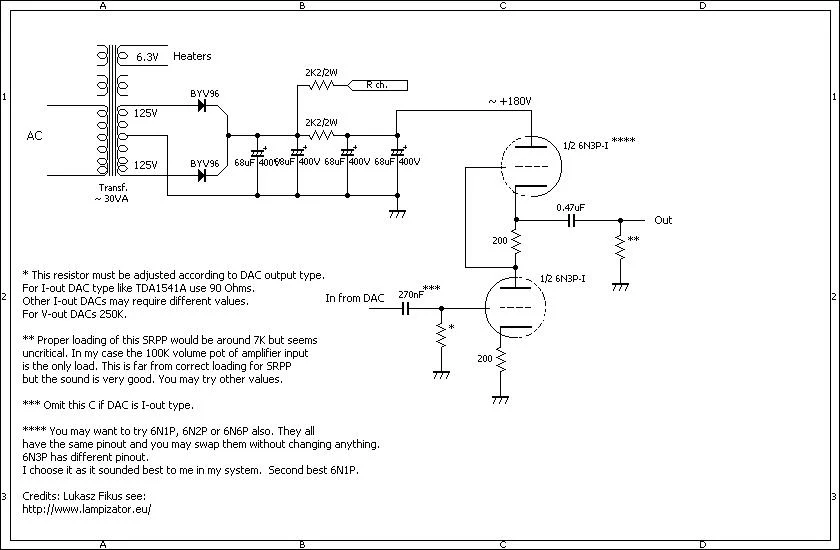
Here is a clean schematic of one version from one of the guys (Lukas Fikus) who is most famous for starting the quest for a perfect tube output for CD players.
1748567264611.webp
 
Last edited:
So it looks like the typical approach is a small resistor value for I to V conversion followed by some gain. 33 ohms seems to be best for "low distortion" which will produce a voltage of 66mV peak. To amplify this to 2V peak requires a gain of 30 times.

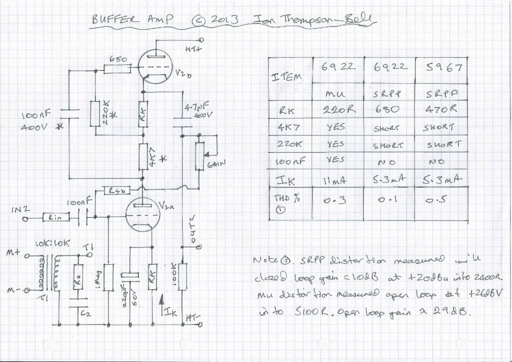
SRPP stages have great drive capability but they do have a high distortion level. A better topology might be to use a mu follower. This has higher gain and much lower distortion than an SRPP using the same tube. For a gain of 30 times you probably cannot do better than an ECC88. Here is a buffer circuit I designed a decade ago.

BufferAmpCctscaled.webp


At first glance the SRPP looks to have the lowest distortion but that is only because the test was done with 20dB of negative feedback so the open loop distortion is near 1% at the level quoted. The mu follower distortion is measured a 20V rms driving a 5100R load. For the CD player the level will be 20dB lower as will be the distortion and into say a 50K load it will be lower still.

Cheers

Ian
 
So it looks like the typical approach is a small resistor value for I to V conversion followed by some gain. 33 ohms seems to be best for "low distortion" which will produce a voltage of 66mV peak. To amplify this to 2V peak requires a gain of 30 times.

SRPP stages have great drive capability but they do have a high distortion level. A better topology might be to use a mu follower. This has higher gain and much lower distortion than an SRPP using the same tube. For a gain of 30 times you probably cannot do better than an ECC88. Here is a buffer circuit I designed a decade ago.

View attachment 6

At first glance the SRPP looks to have the lowest distortion but that is only because the test was done with 20dB of negative feedback so the open loop distortion is near 1% at the level quoted. The mu follower distortion is measured a 20V rms driving a 5100R load. For the CD player the level will be 20dB lower as will be the distortion and into say a 50K load it will be lower still.

Cheers

Ian
My preamp has a 50K input so I suppose the it meets the best case load requirement.
 
My preamp has a 50K input so I suppose the it meets the best case load requirement.
Yes, that should be pretty much ideal. The original is designed to work from a 300V HT supply but you don't need it to be that high for a maximum 2V output so the cathode resistors might need tweaking to maintain the same quiescent current with a lower supply voltage.

Cheers

Ian
 
Yes, that should be pretty much ideal. The original is designed to work from a 300V HT supply but you don't need it to be that high for a maximum 2V output so the cathode resistors might need tweaking to maintain the same quiescent current with a lower supply voltage.

Cheers

Ian
I have two different 120v 60 hz toroidal transformers. One is 100VA and has two 175v and two 6.3v secondaries. The other is 50VA and has two 150V and two 6.3v secondaries. I don't know which would be better to use or if either is suitable for that matter. As I said, I need help (lots of help). :) Here are the spec sheets for each.
https://www.antekinc.com/as-1t175-100va-175v-transformer/
https://www.antekinc.com/as-05tc150-50va-150vx2-transformer/

I am considering building this PS for whatever tube output circuit I decide on. Scroll down in ebay listing for details.
https://www.ebay.com/itm/146473988873

I bought his previous version of the PS last year but never built it because I got overwhelmed and side tracked. The listing for the PS board I bought last year is below.
https://www.ebay.com/itm/144817864498?var=444039060932

Do you think the new board would be a worthwhile improvement?
 
Last edited:
Using power amp PSU for low level amps make the whole thing take up a lot of space.
I'd go for a SMPS with a post regulator, even a big chassis mounted dropping resistor, 180V power zener diode and a ~220uF cap (common part in forward converters) for low noise, and simplicity.
6DJ8 is a good choice, very linear with a FET 10mA constant current load, also easy to make, One tube will do for both channels.
 
I have two different 120v 60 hz toroidal transformers. One is 100VA and has two 175v and two 6.3v secondaries. The other is 50VA and has two 150V and two 6.3v secondaries. I don't know which would be better to use or if either is suitable for that matter. As I said, I need help (lots of help). :) Here are the spec sheets for each.
https://www.antekinc.com/as-1t175-100va-175v-transformer/
https://www.antekinc.com/as-05tc150-50va-150vx2-transformer/

The 100VA is definitely overkill and the 50VA is still way more than you will need. It is a pity that Antek do not to a 25VA transformer which would have been ideal.
I am considering building this PS for whatever tube output circuit I decide on. Scroll down in ebay listing for details.
https://www.ebay.com/itm/146473988873

I bought his previous version of the PS last year but never built it because I got overwhelmed and side tracked. The listing for the PS board I bought last year is below.
https://www.ebay.com/itm/144817864498?var=444039060932

That is a very complex supply for a simple low current preamp. An HT supply consisting of a DIP bridge rectifier and reservoir capacitor followed by three RC stages of ripple reduction will be more than adequate. My HT250 design would be more than adequate and much simpler (details attached)

Cheers

Ian
 

Attachments

The 100VA is definitely overkill and the 50VA is still way more than you will need. It is a pity that Antek do not to a 25VA transformer which would have been ideal.


That is a very complex supply for a simple low current preamp. An HT supply consisting of a DIP bridge rectifier and reservoir capacitor followed by three RC stages of ripple reduction will be more than adequate. My HT250 design would be more than adequate and much simpler (details attached)

Cheers

Ian
That is definitely simpler and would be less costly to build. I am handicapped by my lack of knowledge. I have no clue about how to change components to get different output voltages when starting with a given input voltage from a transformer. I once tried to get some help with how to go about that and asked about using resistors for a voltage divider and was ridiculed for thinking that "wasting" energy and "creating heat" without advice on how to avoid doing that. Sigh. I eventually just gave up.

I decided to build the PS that I showed because I wanted to have a "one size fits all: PS that is adjustable and I can use for any project I decide to ever build. Never know when I might decide to try to build a power amp.

I don't know why Antek doesn't build an off the shelf 25VA transformer that has secondary output options like their larger transformers. I understand that the current ratings would be lower and maybe they think that would reduce sales making stocking them impractical.

They will build custom transformers to any spec requested but that comes at a higher cost than their off the shelf transformers. The prices of their off the shelf transformers are the lowest I have ever found for similar build quality. If you know of any others than I might consider, I would appreciate a link or just the company. Hammond and others that I have looked at are a lot more $$$.
 
Last edited:
Using power amp PSU for low level amps make the whole thing take up a lot of space.
I'd go for a SMPS with a post regulator, even a big chassis mounted dropping resistor, 180V power zener diode and a ~220uF cap (common part in forward converters) for low noise, and simplicity.
6DJ8 is a good choice, very linear with a FET 10mA constant current load, also easy to make, One tube will do for both channels.
Thanks. See my reply to Ian above.
 
Last edited:
So it looks like the typical approach is a small resistor value for I to V conversion followed by some gain. 33 ohms seems to be best for "low distortion" which will produce a voltage of 66mV peak. To amplify this to 2V peak requires a gain of 30 times.

SRPP stages have great drive capability but they do have a high distortion level. A better topology might be to use a mu follower. This has higher gain and much lower distortion than an SRPP using the same tube. For a gain of 30 times you probably cannot do better than an ECC88. Here is a buffer circuit I designed a decade ago.

View attachment 6

At first glance the SRPP looks to have the lowest distortion but that is only because the test was done with 20dB of negative feedback so the open loop distortion is near 1% at the level quoted. The mu follower distortion is measured a 20V rms driving a 5100R load. For the CD player the level will be 20dB lower as will be the distortion and into say a 50K load it will be lower still.

Cheers

Ian
I am trying to learn the pros and cons of different circuits that can be used for building an tube output that will take 2mA and convert it to voltage that is usable to feed the grid of a tube and output about 2v.

I started when I ran across Lukas Fiscus' "Lampizator.eu" website a few years ago. He only used SRPP circuits with AC anode and heater voltages I think because they are simple. He no longer updates his DIY site because he now has a high end gear company selling DACs that cost $5k - $20k and are not simple at all in their designs. LOL

In any case, many people were critical of his DIY designs and ridiculed them as "never going to sound good". In spite of that, many people built them and claimed very good results.

Then I heard about others who had developed other circuits for use as tube outputs for DACs and CD players. John Broskie used what he called the Aikido preamp.

Another has been Thorsten Loesch who used this design:
1748735908320.webp
 
That is definitely simpler and would be less costly to build. I am handicapped by my lack of knowledge. I have no clue about ho to change components to get different output voltages when starting with a given input voltage from a transformer. I once tried to get some help with how to go about that and asked about using resistors for a voltage divider and was ridiculed for thinking that "wasting" energy and "creating heat" without advice on how to avoid doing that. Sigh. I ust gave up.

That is a pity. Unfortunately, it is a sad fact of modern life the "helping" others so often becomes quite aggressive. I think the people who do this would think twice about it if they were face to face with you. Just one of the many pitfalls of the internet. As a man once said "manners maketh man".
I decided to build the PS that I showed because I want to have a "one size fits all: PS that is adjustable and I can use for any project I decide to ever build. Never know when I might decide to try to build a power amp.
I don't know how much experience you have of building tube circuits but as I am sure you are aware some of the voltages involved are lethal and they are around in abundance in an HT supply PCB. The PSU board you are planning to build is quite complex and full of easily blown up semiconductors. If this is your first high voltage build I urge you to take great care. There are some excellent on line resources for newcomers to tube DIY
I don't know why Antek doesn't build an off the shelf 25VA transformer that has secondary output options like their larger transformers. I understand that the current ratings would be lower and maybe they think that would reduce sales making stocking them impractical.
I have done a lot of searching for transformers for tube preamp and mixer supplies over the years. The bottom line is there are few if any that combine HT and heater windings at 25VA or less. Here is a link to a discussion of this topic at groupDIY:

https://groupdiy.com/threads/ht-transformers-for-vacuum-tube-preamps.75793/
They will build custom transformers to any spec requested but that comes at a higher cost than their off the shelf transformers. The prices of their off the shelf transformers are the lowest I have ever found for similar build quality. If you know of any others than I might consider, I would appreciate a link or just the company. Hammond and others that I have looked at are a lot more $$$.
I once had made a batch of ten custom preamp toroid transformers. I sold them at cost price and it took me five years to sell them all.

Cheers

Ian
 
That is definitely simpler and would be less costly to build. I am handicapped by my lack of knowledge. I have no clue about ho to change components to get different output voltages when starting with a given input voltage from a transformer. I once tried to get some help with how to go about that and asked about using resistors for a voltage divider and was ridiculed for thinking that "wasting" energy and "creating heat" without advice on how to avoid doing that. Sigh. I ust gave up.

I decided to build the PS that I showed because I want to have a "one size fits all: PS that is adjustable and I can use for any project I decide to ever build. Never know when I might decide to try to build a power amp.
I'd like to appologize for the jerks that tried to belittle you. I'm sure they weren't born with knowledge of how to build circuits.

Perhaps a bit of "design philosophy" would be helpful. If you're looking to design a universal supply, it might be a good idea to start with a variable voltage (think the wiper of a pot set across the filter capacitor to ground with adequate power dissipation), and follow that with an amplifier that would give you adequate current for the loads you are driving.

As has been noted, tube circuits have generally high voltages in them - the nature of the beast. And they also run hot - those cathode heaters will warm up a small room fairly quickly. So being concerned about resistor networks and their dissipation is a secondary issue. Just do the math (P=IE) to insure the resistors can handle the dissipation they're going to have to.

I haven't designed a tube circuit in ages, and that was a CRT (oscilloscope display tube in my case), and the voltages definitely made me stay alert while I was doing what I had to do to make the thing work.

And I've made plenty of mistakes and let the smoke get out of many, many parts over the course of my career. That's just part of learning how. Just don't let the smoke get out of you!
 
I'd like to appologize for the jerks that tried to belittle you. I'm sure they weren't born with knowledge of how to build circuits.

Perhaps a bit of "design philosophy" would be helpful. If you're looking to design a universal supply, it might be a good idea to start with a variable voltage (think the wiper of a pot set across the filter capacitor to ground with adequate power dissipation), and follow that with an amplifier that would give you adequate current for the loads you are driving.

As has been noted, tube circuits have generally high voltages in them - the nature of the beast. And they also run hot - those cathode heaters will warm up a small room fairly quickly. So being concerned about resistor networks and their dissipation is a secondary issue. Just do the math (P=IE) to insure the resistors can handle the dissipation they're going to have to.

I haven't designed a tube circuit in ages, and that was a CRT (oscilloscope display tube in my case), and the voltages definitely made me stay alert while I was doing what I had to do to make the thing work.

And I've made plenty of mistakes and let the smoke get out of many, many parts over the course of my career. That's just part of learning how. Just don't let the smoke get out of you!
When I listen to my stereo system in the winter I turn the HVAC thermostat down in the house. Keeps my wife from asking why the power bill went up. ;)

I bought an adjustable, regulated PSU PCB that is marked with component values; so, it is kinda like paint by numbers art. It is the tube output circuit that I mainly need help with.

I have always followed the one hand rule when I take the cover off of my amps to check the bias of the tubes. About 35 years ago, I had a VOM probe slip off on a test point in a tube amp and make contact with the chassis. The spark was impressive and it welded the tip of the probe to the chassis. I bought some insulated clip leads for my VOM after that. Now, when I have to check inside my gear, I try to drain the capacitors by playing music and pulling the mains plug to drain the capacitors. I don't turn the power back on on until I have the clips attached.
 
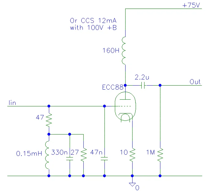
This is an interesting circuit that exploits an inductor anode load which allows the HT voltage to be reduced significantly. I am not sure of the purpose of the LCR circuit in the grid - perhape to compensate for poor HF performance of the anode inductor. The 160H inductor capable of sustained 12mA dc will be large and very expensive.

Cheers

Ian
 
I'd like to appologize for the jerks that tried to belittle you. I'm sure they weren't born with knowledge of how to build circuits.

Perhaps a bit of "design philosophy" would be helpful. If you're looking to design a universal supply, it might be a good idea to start with a variable voltage (think the wiper of a pot set across the filter capacitor to ground with adequate power dissipation), and follow that with an amplifier that would give you adequate current for the loads you are driving.

As has been noted, tube circuits have generally high voltages in them - the nature of the beast. And they also run hot - those cathode heaters will warm up a small room fairly quickly. So being concerned about resistor networks and their dissipation is a secondary issue. Just do the math (P=IE) to insure the resistors can handle the dissipation they're going to have to.

I haven't designed a tube circuit in ages, and that was a CRT (oscilloscope display tube in my case), and the voltages definitely made me stay alert while I was doing what I had to do to make the thing work.

And I've made plenty of mistakes and let the smoke get out of many, many parts over the course of my career. That's just part of learning how. Just don't let the smoke get out of you!
When I listen to my current system I turn the thermostat down in the house. Keeps my wife from asking why the power bill went up. ;)

I bought an adjustable, regulated PSU PCB that is marked with component values; so, it is kinda like paint by numbers art. It is the tube output circuit that I mainly need help with.

I have always followed the one hand rule when I take the cover off of my amps to check the bias of the tubes. About 35 years ago, I had a VOM probe slip off on a test point in a tube amp and make contact with the chassis. The spark was impressive and it welded the tip of the probe to the chassis. I bought some insulated clip leads for my VOM after that. Now, when I have to check inside my gear, I try to drain the capacitors by playing music and pulling the mains plug to drain the capacitors. I don't turn the power back on on until I have the clips attached.
 
This is an interesting circuit that exploits an inductor anode load which allows the HT voltage to be reduced significantly. I am not sure of the purpose of the LCR circuit in the grid - perhape to compensate for poor HF performance of the anode inductor. The 160H inductor capable of sustained 12mA dc will be large and very expensive.

Cheers

Ian
I had already decided to not use a circuit that required inductors because of the cost and component size. When Thorsten designed that circuit, he had a source for reasonably priced transformers and chokes that you probably know of, Danbury Electronics, which has since gone out of business. He also used inductors in his PSU for filtering and smoothing of AC.
 
Using power amp PSU for low level amps make the whole thing take up a lot of space.
I'd go for a SMPS with a post regulator, even a big chassis mounted dropping resistor, 180V power zener diode and a ~220uF cap (common part in forward converters) for low noise, and simplicity.
6DJ8 is a good choice, very linear with a FET 10mA constant current load, also easy to make, One tube will do for both channels.
My goal is to try to build the "best" possible tube output for my CD player. :) I wanted to avoid SMPS because I have read that they are noisy.

I did buy an adjustable one for $40 USD to use when I was building an ultrasonic record cleaner. That turned out to be an expensive project but still was only about 1/2 of what commercial record cleaners with the same capabilities cost a the time.
 
My goal is to try to build the "best" possible tube output for my CD player. :) I wanted to avoid SMPS because I have read that they are noisy.
Some SMPS undoubtedly are noisy and not so long ago many of them ran at frequencies not much above the audio band. I used linear heater supplies for years until I started building bigger mixers and discovered I was going to need a 10 amp linear heater supply and it would only be about 50% efficient. I tried many types of SMPS until I came across the ones made by Meanwell. They are very quiet (they run at over 100KHz) and when I have used them as heater supplies it resulted in the quietest noise figures I have ever measured. For your project one of their small encapsulated PCB mount 10W units should suffice.

Cheers

Ian
 
Some SMPS undoubtedly are noisy and not so long ago many of them ran at frequencies not much above the audio band. I used linear heater supplies for years until I started building bigger mixers and discovered I was going to need a 10 amp linear heater supply and it would only be about 50% efficient. I tried many types of SMPS until I came across the ones made by Meanwell. They are very quiet (they run at over 100KHz) and when I have used them as heater supplies it resulted in the quietest noise figures I have ever measured. For your project one of their small encapsulated PCB mount 10W units should suffice.

Cheers

Ian
That would solve the heater supply need. What would you use for the HT supply?
 
SMPS running at typical 250KHz is unlikely to bring much grief into audio, Some bats may be bothered.
For a couple of tube heaters an LM317 is good enough. Avoiding AC fields is always a plus. Dropout times the current equals the size of the heatsink.
Minimum 1.5V dropout is needed for this chip.
Building "the best possible"may be OK given the constraints, performance, budget, time, size etc. In audio circles "best" is in the ears of the beholder.

What is your Line input load impedance and max (peak) input level?

You can search the Bay for preamp SMPS supplies, should be around $25.
 
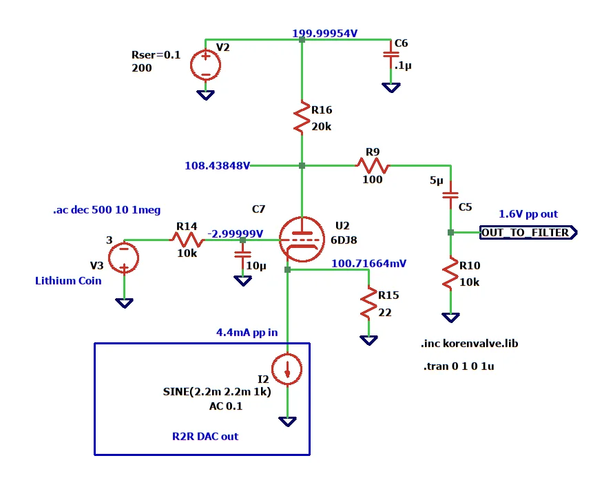
A resistive load on the R2R output is not ideal but possible. A tube grounded grid has been suggested by some. A 6DJ8 could work, with cathode as input.
I could not find a good model for an R2R DAC output, so I used a current source in parallel with a 22 ohm resistor, to make the sim work. It may not be needed. Substitute with a small diode, to protect DAC, 1N914 etc.
SPICE current sources are idealized unbounded mathematical devices, they can produce kilovolts.
1748817468503.webp
 
Last edited:
Back
Top