Having trouble navigating this website.

Just wanted to check in and see how the hunt for circuits using the 5840 tube is going. Hope you’ve found some interesting leads or maybe even hit a snag. Let me know what’s up.
 
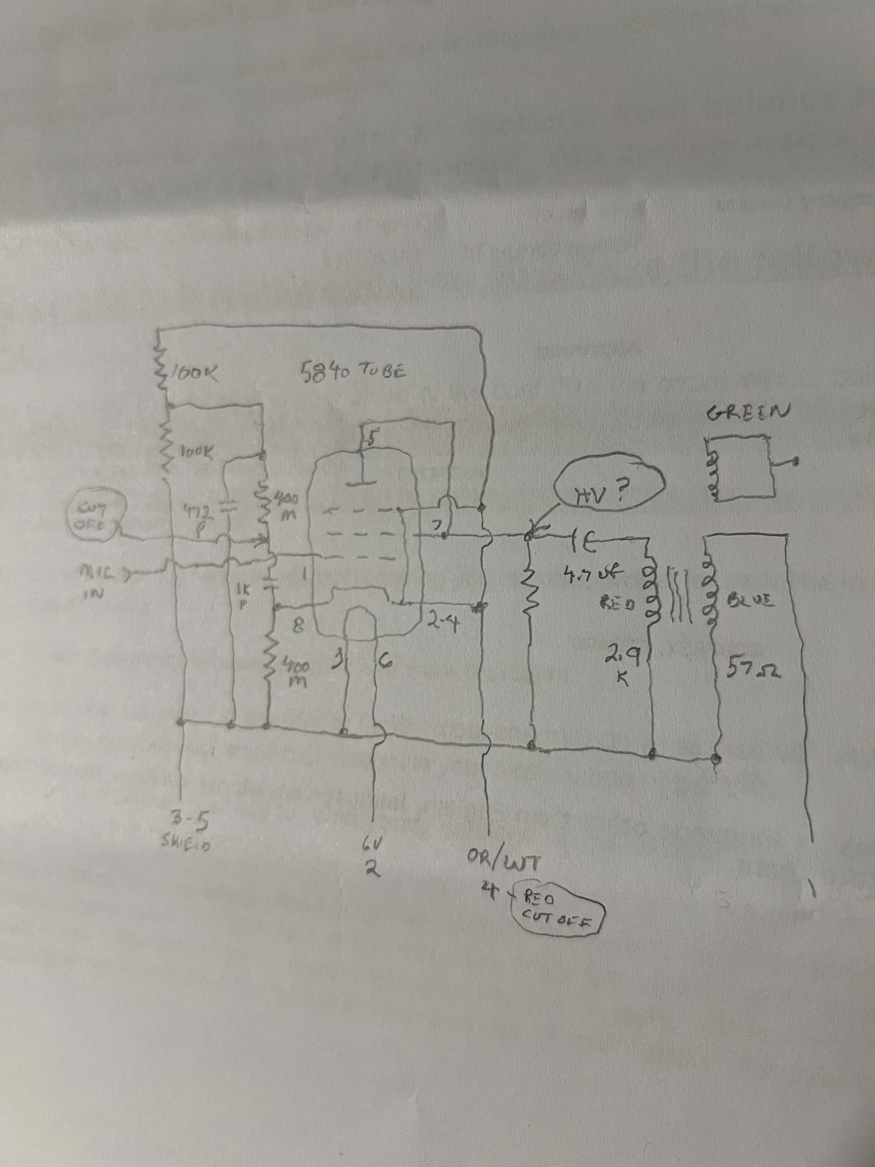
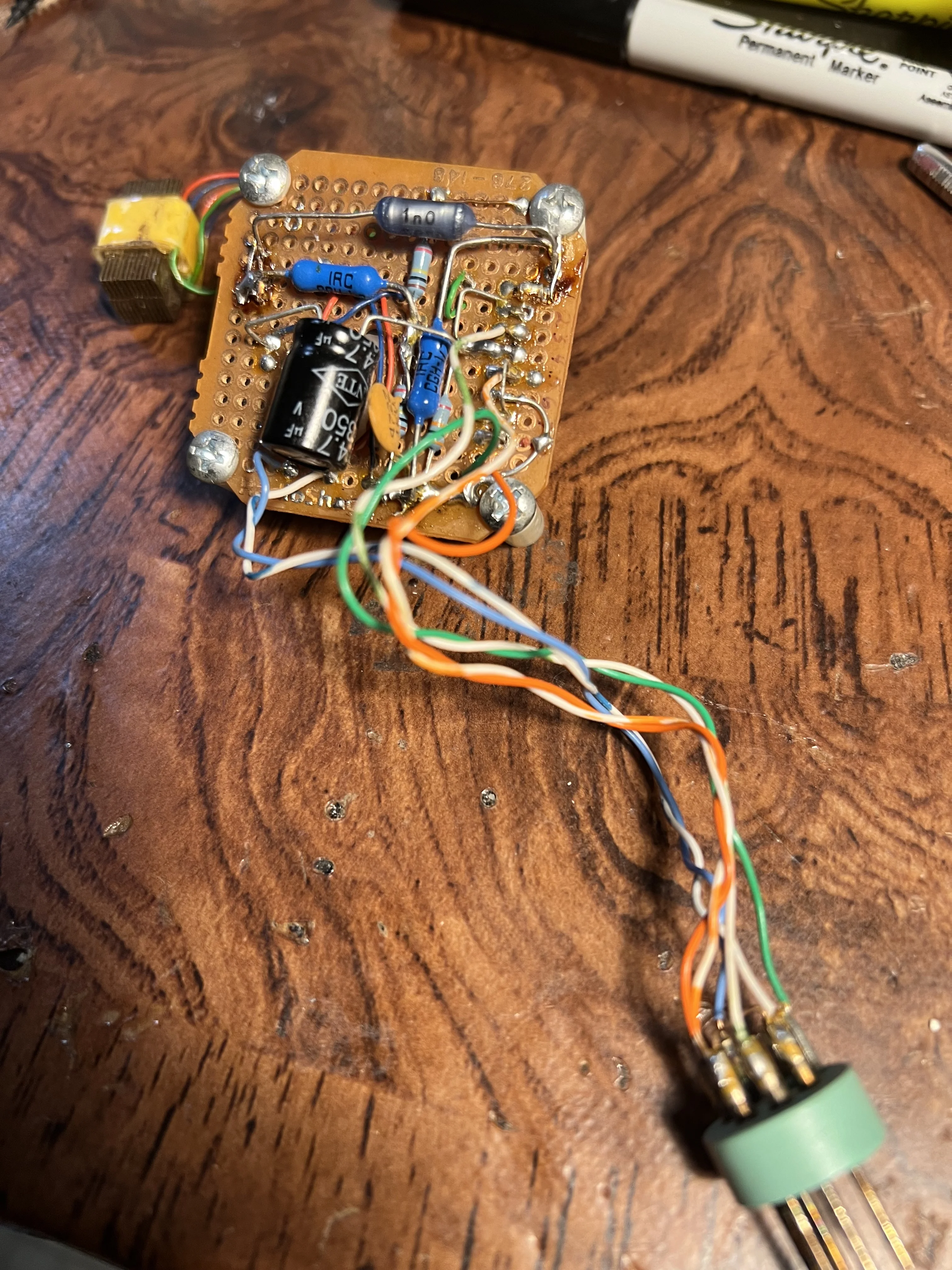
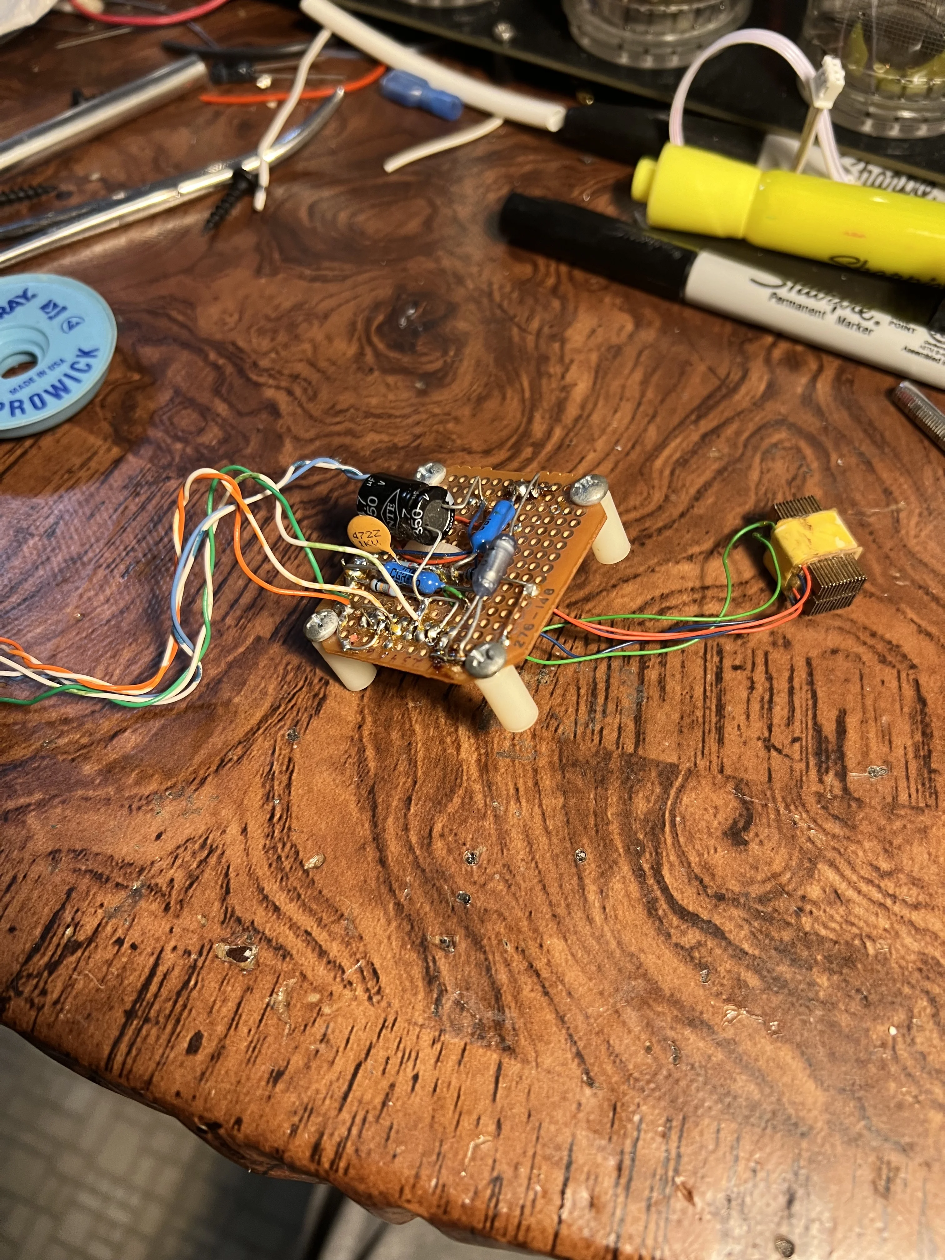
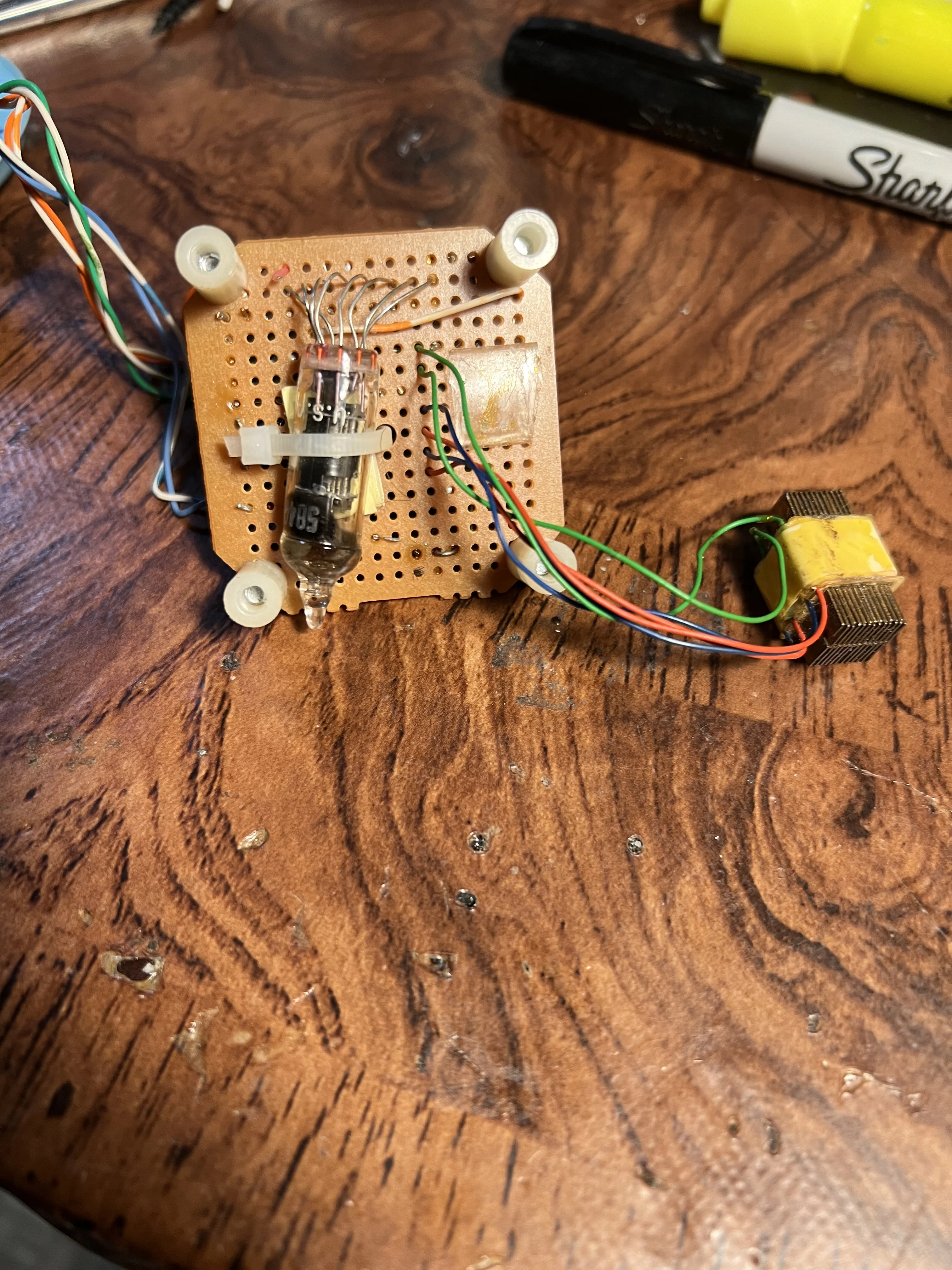
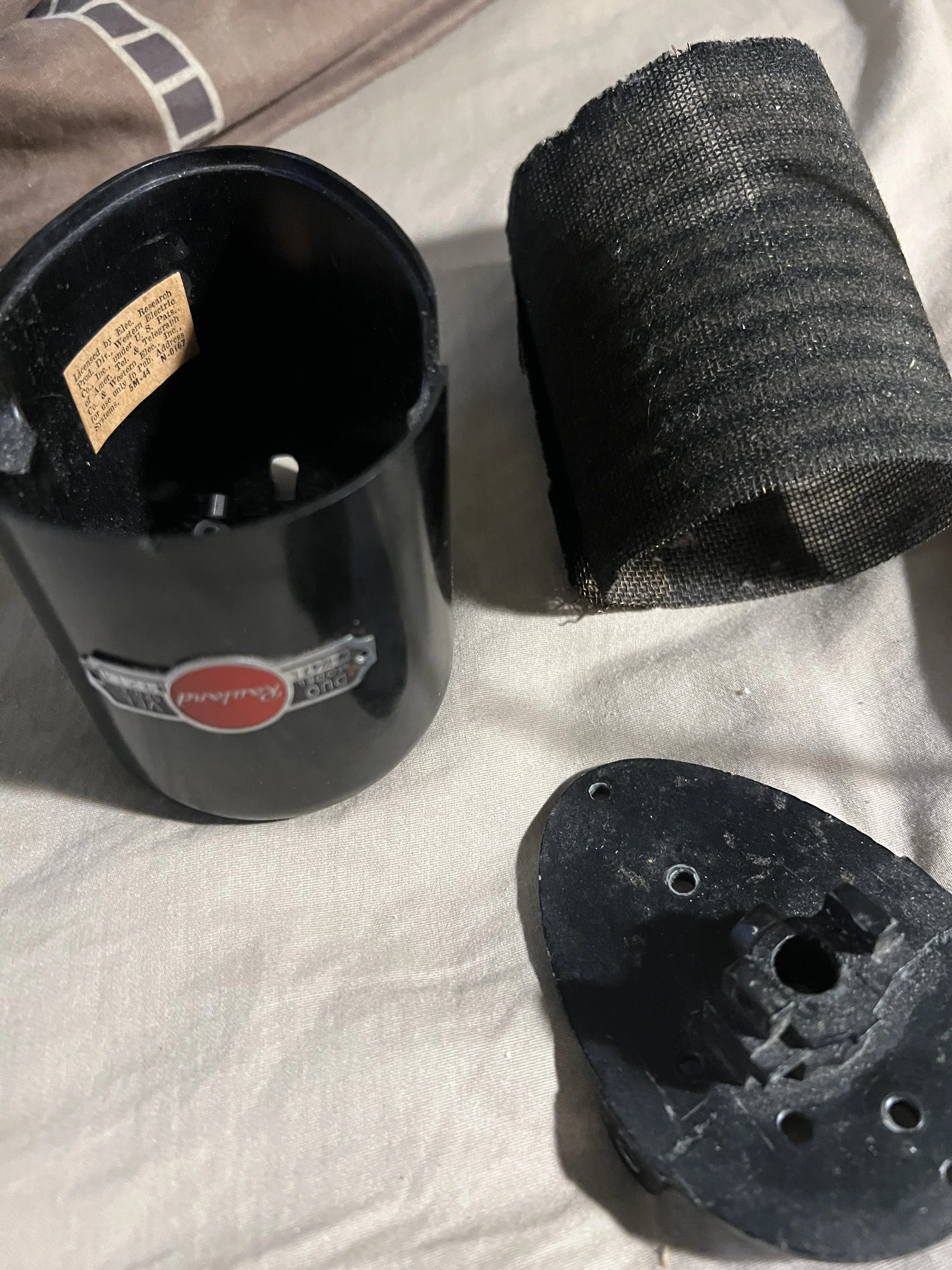
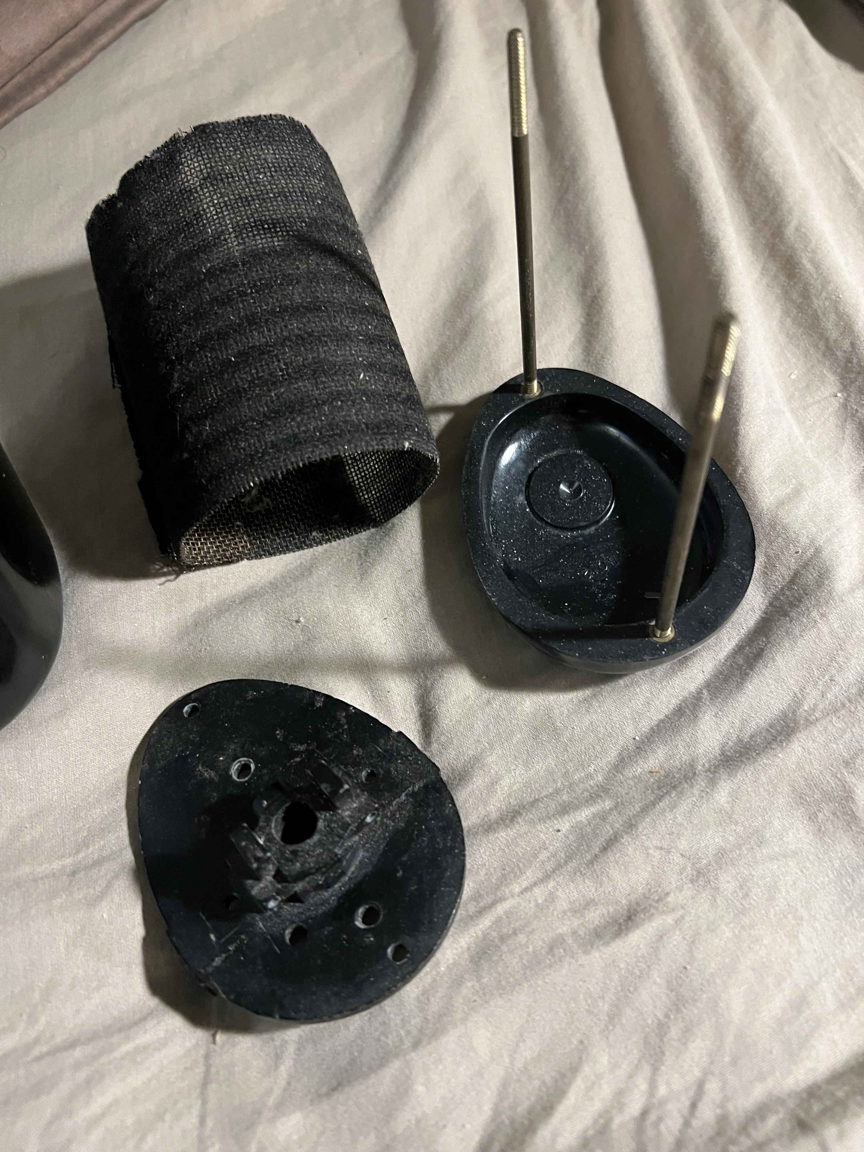
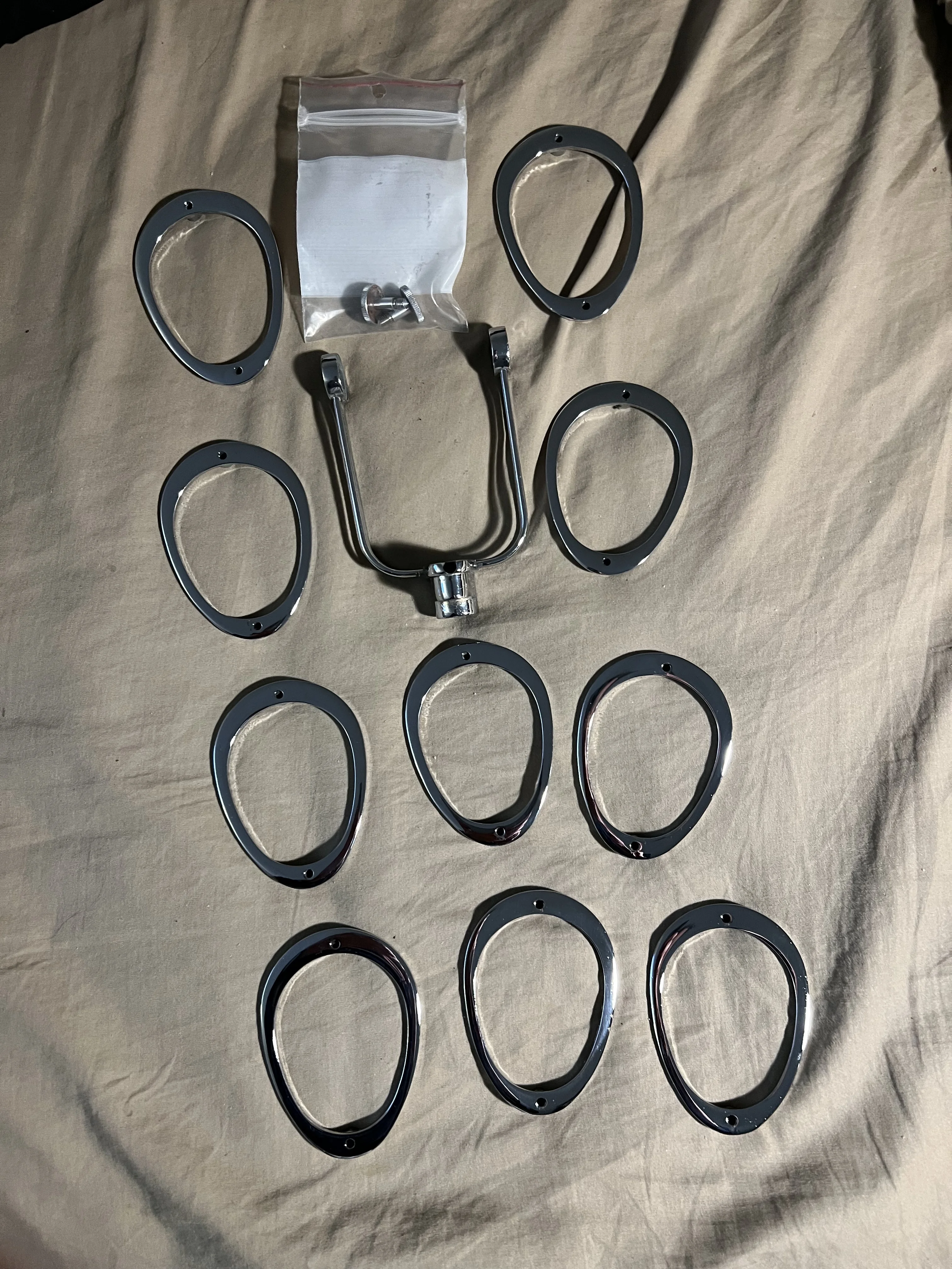
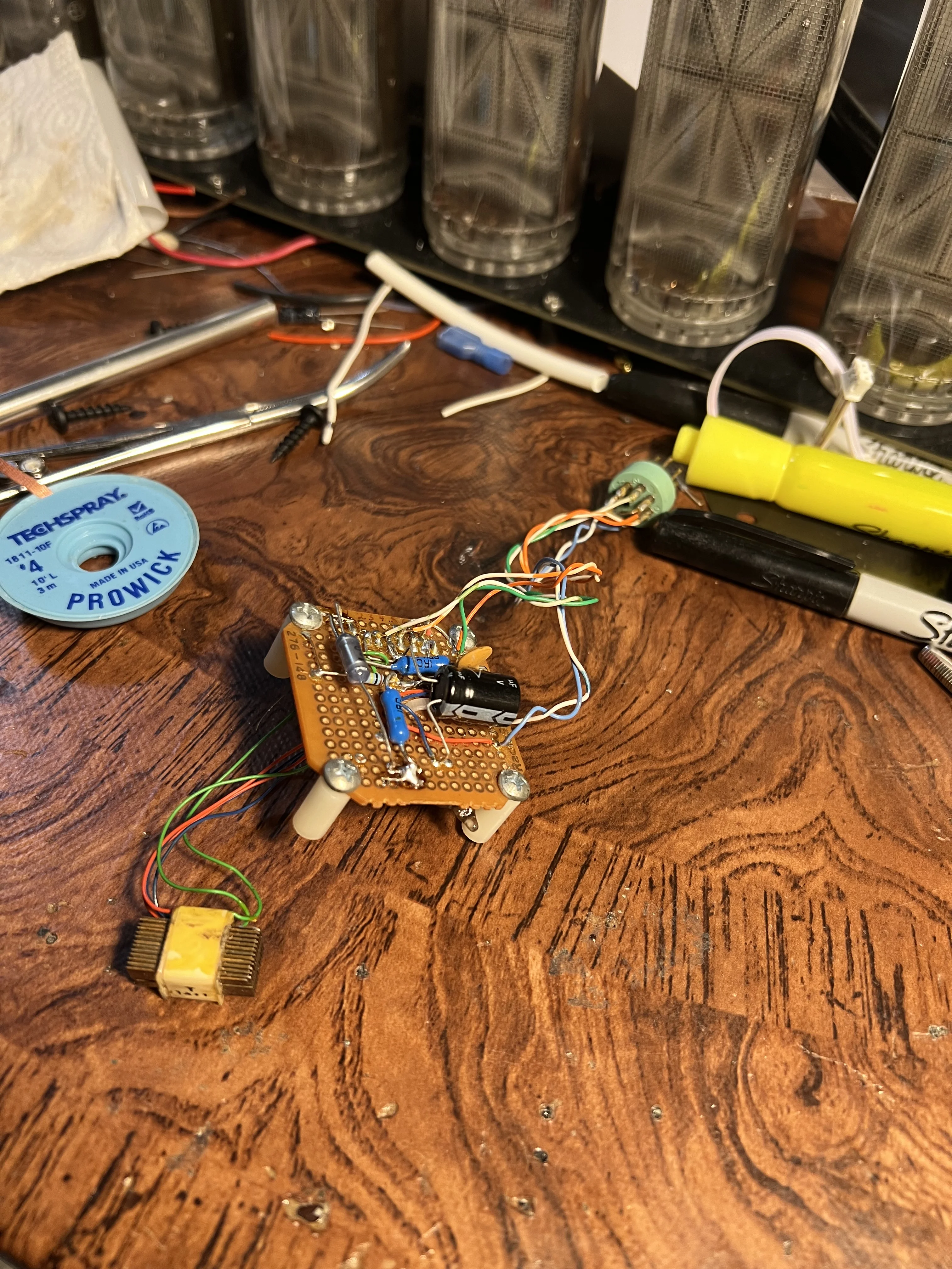
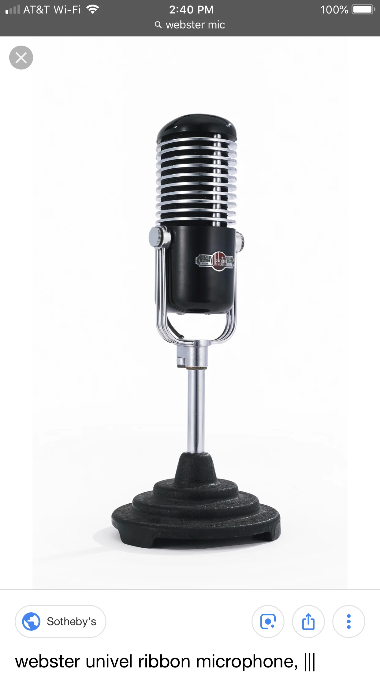
I have this circuit I bought years ago. And this empty mic shell. I had the shiny bits chrome plated. Trying to figure out the preamp circuit.
IMG_0704.webp
IMG_0705.webp
IMG_0706.webp
IMG_0707.webp
IMG_0707.webp
IMG_0709.webp
IMG_0710.webp
IMG_0711.webp
IMG_0711.webp
 
That setup looks super cool! I really wish I could help out, especially with the preamp part. Fingers crossed that more people see this and chime in with their insights and experiences.
 
It’s been a bit since I worked on any tube circuits, but it looks like the resistor that goes to ground from the point marked “HV?” should go to a fairly high positive voltage. I’d say about +80V but certainly less than the voltage rating of the coupling capacitor going to the transformer.
 
Thanks, I just need to find a circuit I can use to put inside the microphone that has a polar switch. I’ve built a power supply unit with +130 and +6 volts. I want to use a 5840 tube as I have a few of them.
 
Are the green windings on the transformer really shorted together?

A polarity switch can be done on the output windings pretty easily. A small DPDT switch can do that for you. If you want a diagram, I can draw one up.
 
Yes, green windings are shorted. I would appreciate a drawing very much. Thank you for your help. I was thinking about a 3 position switch for Omni, figure 8 and cardioid
 
A shorted coil on a transformer is a problem. That will take virtually all the energy going into the primary windings and turn them into heat. There MIGHT be some strange effect that the designer intended, but that’s a strange circuit element.

Changing a mic through those patterns generally means there are multiple capsules (transducers, diaphraghms) in the mic housing that can be switched in and out.

For what it’s worth, my mic designing skills were acquired by osmosis - working in the vicinity of someone actually doing that work, not doing it myself as a professional. I’m pretty sure what I’ve told you so far is right, but it’s limited.
 
Hey, I did some more digging. I hope this can at least serve as a reference.

Here's a simplified polar pattern switching circuit for your 5840 tube microphone:
Basic Polar Pattern Switch Circuit:
Capsule Front Diaphragm → 100MΩ → Grid (Pin 2 of 5840)

0.1µF coupling cap

Capsule Rear Diaphragm → Polar Switch:
Position 1 (Cardioid): → 100MΩ → Ground
Position 2 (Omni): → 100MΩ → +60V (half of +130V via divider)
Position 3 (Figure-8): → 100MΩ → +130V

Voltage Divider for Omni mode:
+130V → 1MΩ → [+60V tap] → 1MΩ → Ground
5840 Tube Connections:

Pin 1: Plate → 100kΩ → +130V
Pin 2: Grid (capsule input via 100MΩ)
Pin 3: Cathode → 2.2kΩ → Ground (+ 47µF bypass cap)
Pins 4,5: Heater → +6V
Pin 7: Output (via transformer primary)

Polar Switch Wiring:
Use a 3-position rotary switch to connect rear diaphragm between ground (cardioid), +60V (omni), or +130V (figure-8) through a 100MΩ resistor.
This gives you switchable patterns using your existing power supply.
 
That’s great to hear! Can't wait to see how it turns out.
 
Back
Top