Hi All.

audioxcel

Active member
Joined
May 27, 2025
Messages
32
Hi, All. My real name is Charlie and I live in Portland, OR. I am a 78 year old guy who has been searching for audio nirvana since about 1985, I have what I consider a pretty good system. Martin Logan Sequels, Mirage BPS400 sub with LFX1 active X-over, Audio Research D70 MkII amp (currently in shop for electrolytic caps replacement), Convergent Audio Technology Signature MkIII preamp. Yamaha PX2 turntable with Ortofon Cadenza black cartridge, Philips CD880 (which I am working on modifying to have tube output in place of IC op amps).

The circuits for the tube output for my CD player is what has brought me to this site. I have never done a project like this and am learning by the seat of my pants. I will need expert help with the design and building of a good tube output. The info I have found started with Lampizator SRPP circuits.

The problem is that Lukas Fiskus who created his Lampizator following never goes into the details of his designs in depth. He published schematics scribbled on scraps of paper and assumed that anyone who built a Lampizator output would have a decent knowledge of tube circuits.

I don't have sufficient knowledge to design the necessary power supplies and basic tube circuits to build a good output for my CD player. On most sites, it seems that more than half of the responses to requests for help turn out to be criticisms of "the circuit concepts" or ridicule the idea of using tubes for a CD player output rather than suggestions that are helpful. I am hoping this site will be different.
 
Last edited:
Hi Charlie, I am a mere 74 years old and have spent the last quarter century working on pro audio tube circuits. In am not familair with the many and varied hifi tube designers but I am happy to hep out decoding and making sense of them for you.

Cheers

Ian
 
Hi Charlie, I am a mere 74 years old and have spent the last quarter century working on pro audio tube circuits. In am not familair with the many and varied hifi tube designers but I am happy to hep out decoding and making sense of them for you.

Cheers

Ian
Thanks, Ian. I will try to find a clear schematic of the circuit I hope to use and post it here.
 
The 44.1/16 source format leaves out detail in which reconstruction leaves room for interpretation, not strictly Harry Nyqvist, but practically. The format was prematurely marketed, IMHO, error correction in real time, rather than delayed post processing.
The D/A conversation also leaves room for variation.
I designed a passive differential output for a Crystal Semi DAC eval board, using air core inductors and PP caps to make an LP filter and terminated with shielded Peerless line transfomers.
Sounded pretty good, but the level was a bit low. (It should perhaps be reworked with higher voltage digital driver buffers.)
Using (selfmade) air core inductors avoided core saturation effects.
The transformer provided added filtering, galvanic isolation, level shifting and single ended outputs.
 
The limited bandwidth of (typical) tube circuits, along with better immunity to modern EMI/EMC/RFI sources make them attractive. The higher voltage output swing also makes them near clip less. Expectations has been a moving target.
 
Woah... LOL. I only want to build a simple SRPP (or other) amplifier circuit that will take the +/-2ma analog output signal from the Philips TDA1541A DAC chip in my Philips CD880 player and make it usable for my stereo system at about 2V.

I suppose I should post this in a different forum. Suggestions?
 
Woah... LOL. I only want to build a simple SRPP (or other) amplifier circuit that will take the +/-2ma analog output signal from the Philips TDA1541A DAC chip in my Philips CD880 player and make it usable for my stereo system at about 2V.

I suppose I should post this in a different forum. Suggestions?
That would be a current output DAC.
Typically this would be interfaced with a current feedback OP amp, like the AD8014 and similar.
The inputs in these is usually an BJT emitter (low impedance), and feedback keeps that input voltage at zero. Easier to do with BJT than vacuum tubes as voltage amplifiers and any voltage on the DAC would be an error, so just hanging a resistor on the DAC output is not optimal.
https://www.tubecad.com/2006/06/blog0070.htm
 
That would be a current output DAC.
Typically this would be interfaced with a current feedback OP amp, like the AD8014 and similar.
The inputs in these is usually an BJT emitter (low impedance), and feedback keeps that input voltage at zero. Easier to do with BJT than vacuum tubes as voltage amplifiers and any voltage on the DAC would be an error, so just hanging a resistor on the DAC output is not optimal.
https://www.tubecad.com/2006/06/blog0070.htm
It is a current output DAC as you have pointed out. The analog outputs feed NE5532 op amps in my Philips CD770 player.

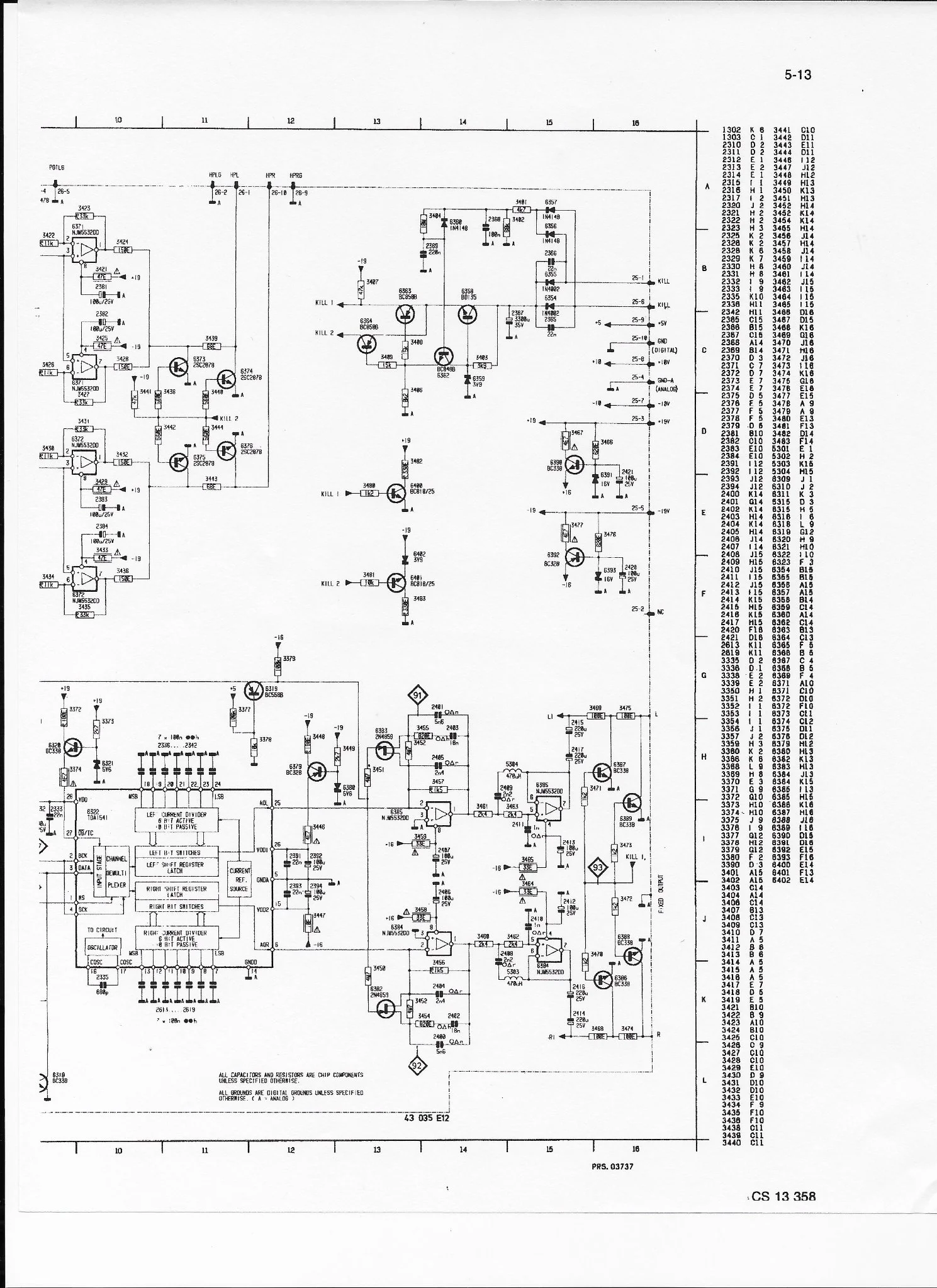
Here is the schematic of the decoder section of he CD880.
1748552392467.webp
 
Philips famously were cost conscious in their products, and the above schematic shows some of it.
Using BJT for signal muting is perhaps not a happy choice, a JFET or a relay would have less leakage.
Few CD players included volume control which would have been nice to drive a PA directly, and could have been done in the digital domain.
There are some low cost "high end" brands that may provide a decent alternative, if the player has a digital output. Else a logic buffer chip and a transformer could be installed, which I did, long time ago.
Now there are many more choices.
The CD output is usually high enough that an amplifier is not needed, but an attenuator. The 5532 IV conversion provides needed buffering and filter driving.
There are some commercial tube output DACs, expensive too. I have not seen any schematic.
I suppose a grounded grid tube circuit, could be tried, somebody may already have.
 
Philips famously were cost conscious in their products, and the above schematic shows some of it.
Using BJT for signal muting is perhaps not a happy choice, a JFET or a relay would have less leakage.
Few CD players included volume control which would have been nice to drive a PA directly, and could have been done in the digital domain.
There are some low cost "high end" brands that may provide a decent alternative, if the player has a digital output. Else a logic buffer chip and a transformer could be installed, which I did, long time ago.
Now there are many more choices.
The CD output is usually high enough that an amplifier is not needed, but an attenuator. The 5532 IV conversion provides needed buffering and filter driving.
There are some commercial tube output DACs, expensive too. I have not seen any schematic.
I suppose a grounded grid tube circuit, could be tried, somebody may already have.
My CD880 was not a "cost conscious" cd player. When it was new, it was the second most expensive player made by Philips. I paid $950USD in 1988. It has many Elna Cerafine caps, the CDM1MkII (all metal) transport, glass lens and TDA1541A S1 DAC, It has a fixed analog output and a variable analog output (remotely controllable volume). It also had a headphone amp. The chassis was heavy metal with a copper shielded cover and back. It weighs 10Kg. The specs were unsurpassed at the time and still near the top ever.

Might the muting circuit have been better with a JFET? I don't know but it has never been an issue for me.

In any case. I want to see how it sounds with a tube output instead of chip op amps. Will it sound better? Maybe and maybe not but there is only one way to find out. I need help to build the best designed tube output I can. :)
 
Last edited:
880 has a digital out, you could of course use with an external DAC.
Interfacing an R2R output with anything other than a proper IV converter is a compromise. Any voltage on the R2R output is an error term.
A faster transimpedance amp from Analog Devices may increase accuracy.
A better reconstruction filter may also be in order.
A voltage output DAC would be easy to adapt to a tube stage.
A 6DJ8 at 10mA per plate with a 180V supply would be 4W of power, . Heater power 6.3V at 0.365A is 2.3W, hopefully regulated DC.
100VA or even 25 is overkill, larger size, larger 50/60 Hz stray fields, unless the PSU is remoted.
As the source is digital, and the IV converter signal is quite high, not much amplification is needed. With a decent (tube) preamp, a post DAC tube stage may be a moot point.
 
I intend to use two separate external chassis, one for the PS and another for the amplification circuit.
 
Also check the DiYaudio forum, they have a lot on this subject.
To drive a small tube at this level, a low power line isolation transformer would do for HV, the heater power is in the wall wart class.
 
A 6DJ8 at 10mA per plate with a 180V supply would be 4W of power, .
If an SRPP or mu follower is used then each tube supports at most only half the HT voltage so with a 180V supply the dissipation per plate is only 0.9W for a total of 1.8W. Even a resistor loaded anode design would again aim for about 50% of the HT voltage at the anode so again the dissipation is only 1.8W
Heater power 6.3V at 0.365A is 2.3W, hopefully regulated DC.

Linear regulators for 6V heaters are terribly inefficient. I standardize on 12V heaters these days and use small MeanWell SMPS for the heater supply.

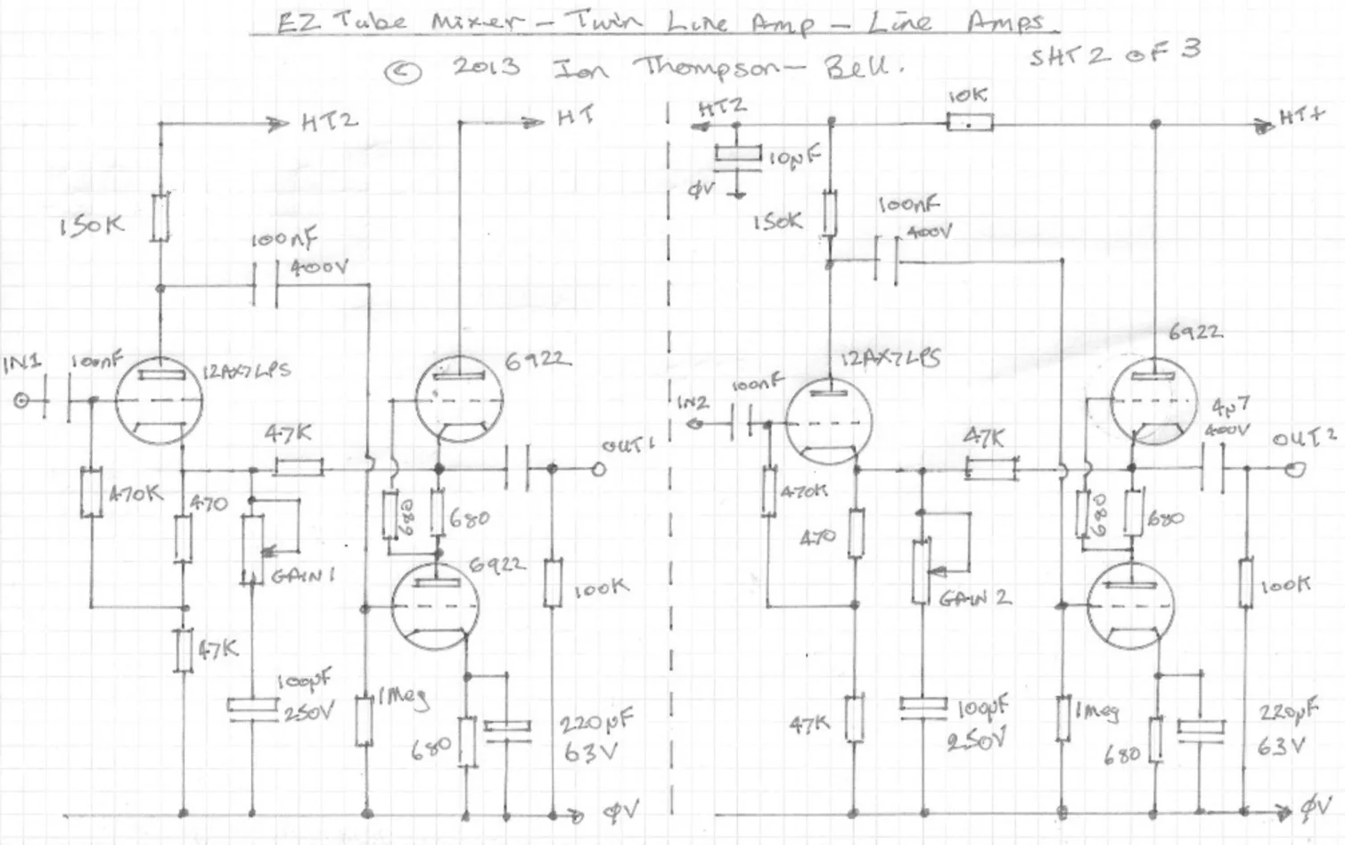
Bottom line is 10mA in an ECC88/6DJ8 is very high and only necessary in the case of the mu follower to minimise the distortion because there is no NFB to help out. OTOH an SRPP makes a much better output stage and will easily drive large signal levels into a load at only 5mA quiescent which drops the total anode dissipation to 0.9W/ The problem is they distort badly but this is easily fixed with the addition of half a 12AX7 at the input and 20dB or so NFB:

TwinLineAmp.webp


Cheers,

Ian
 
If an SRPP or mu follower is used then each tube supports at most only half the HT voltage so with a 180V supply the dissipation per plate is only 0.9W for a total of 1.8W. Even a resistor loaded anode design would again aim for about 50% of the HT voltage at the anode so again the dissipation is only 1.8W


Linear regulators for 6V heaters are terribly inefficient. I standardize on 12V heaters these days and use small MeanWell SMPS for the heater supply.

Bottom line is 10mA in an ECC88/6DJ8 is very high and only necessary in the case of the mu follower to minimise the distortion because there is no NFB to help out. OTOH an SRPP makes a much better output stage and will easily drive large signal levels into a load at only 5mA quiescent which drops the total anode dissipation to 0.9W/ The problem is they distort badly but this is easily fixed with the addition of half a 12AX7 at the input and 20dB or so NFB:

View attachment 9

Cheers,

Ian
This is way over my head but I trust you to give me good info. Can you please show me a mu follower circuit using 33R IV conversion input resistor into the grid of an ECC88 tube with about 2v output to m preamp with 50K inputs?
 
This is way over my head but I trust you to give me good info. Can you please show me a mu follower circuit using 33R IV conversion input resistor into the grid of an ECC88 tube with about 2v output to m preamp with 50K inputs?
I will need to do a couple of simulations to get the component values right. Leave it with me for a couple of days.

Cheers

Ian
 
Back
Top