Morten Gundersen
Member
- Joined
- May 11, 2025
- Messages
- 11
Hi!
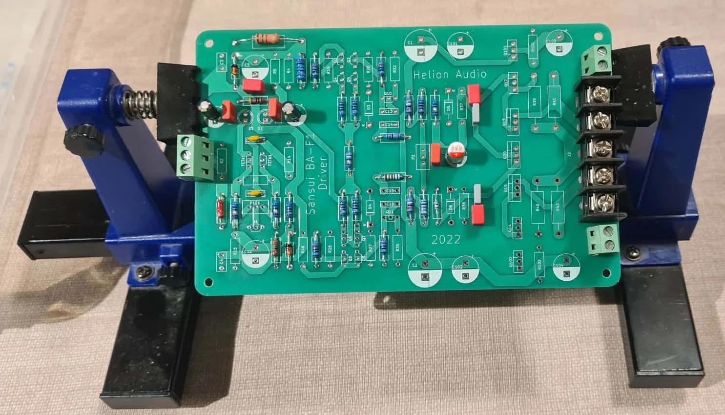
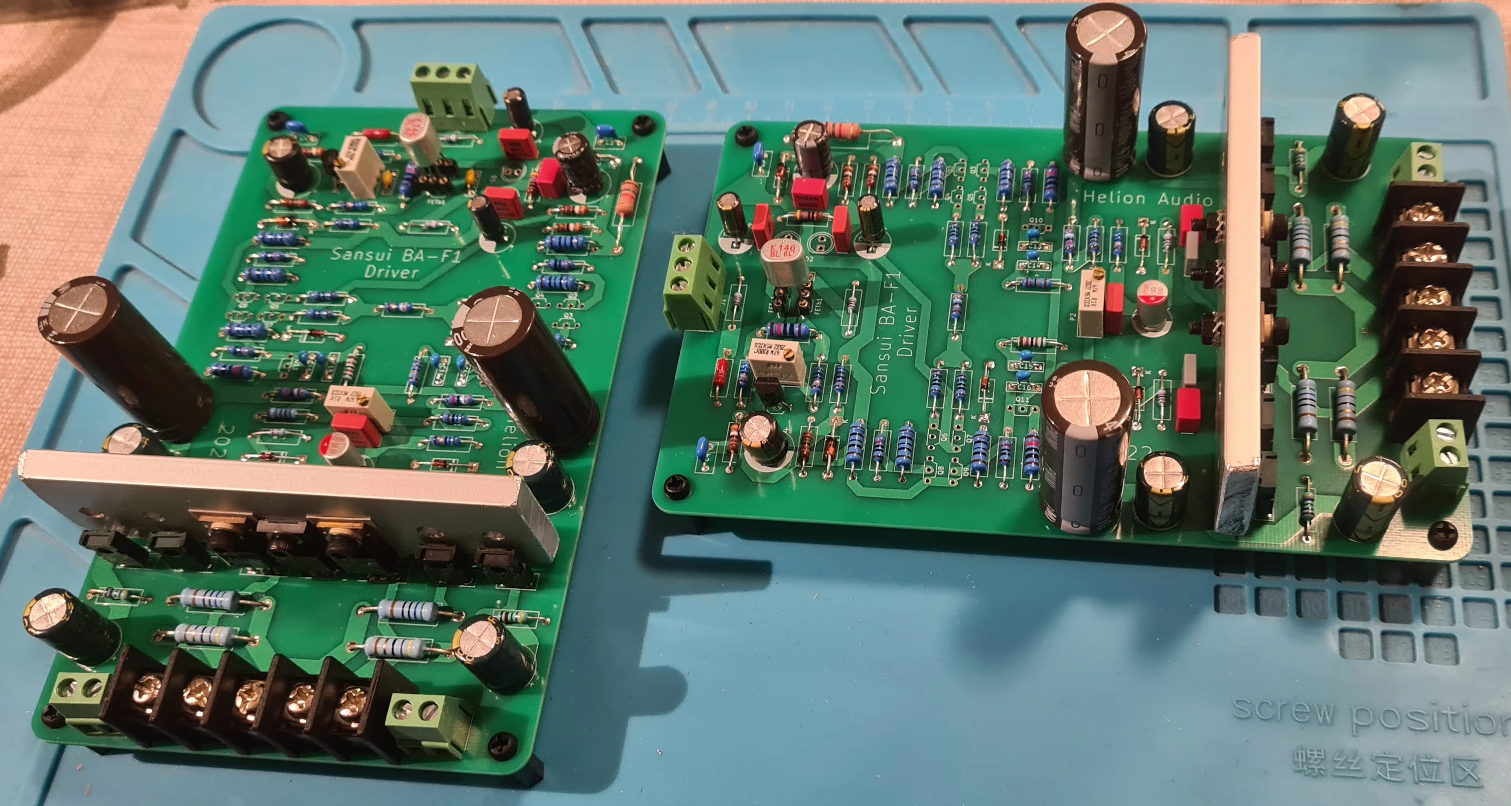
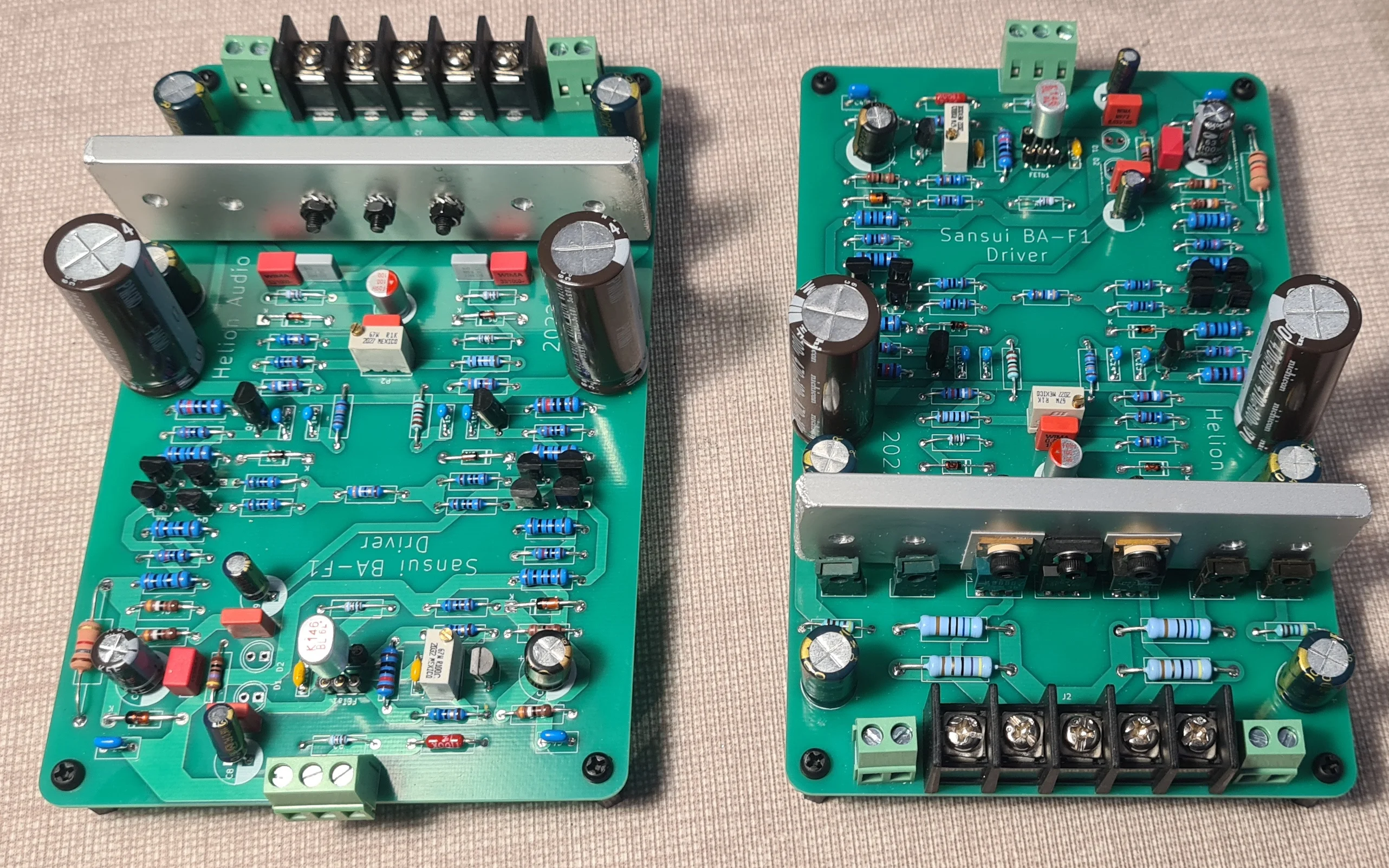
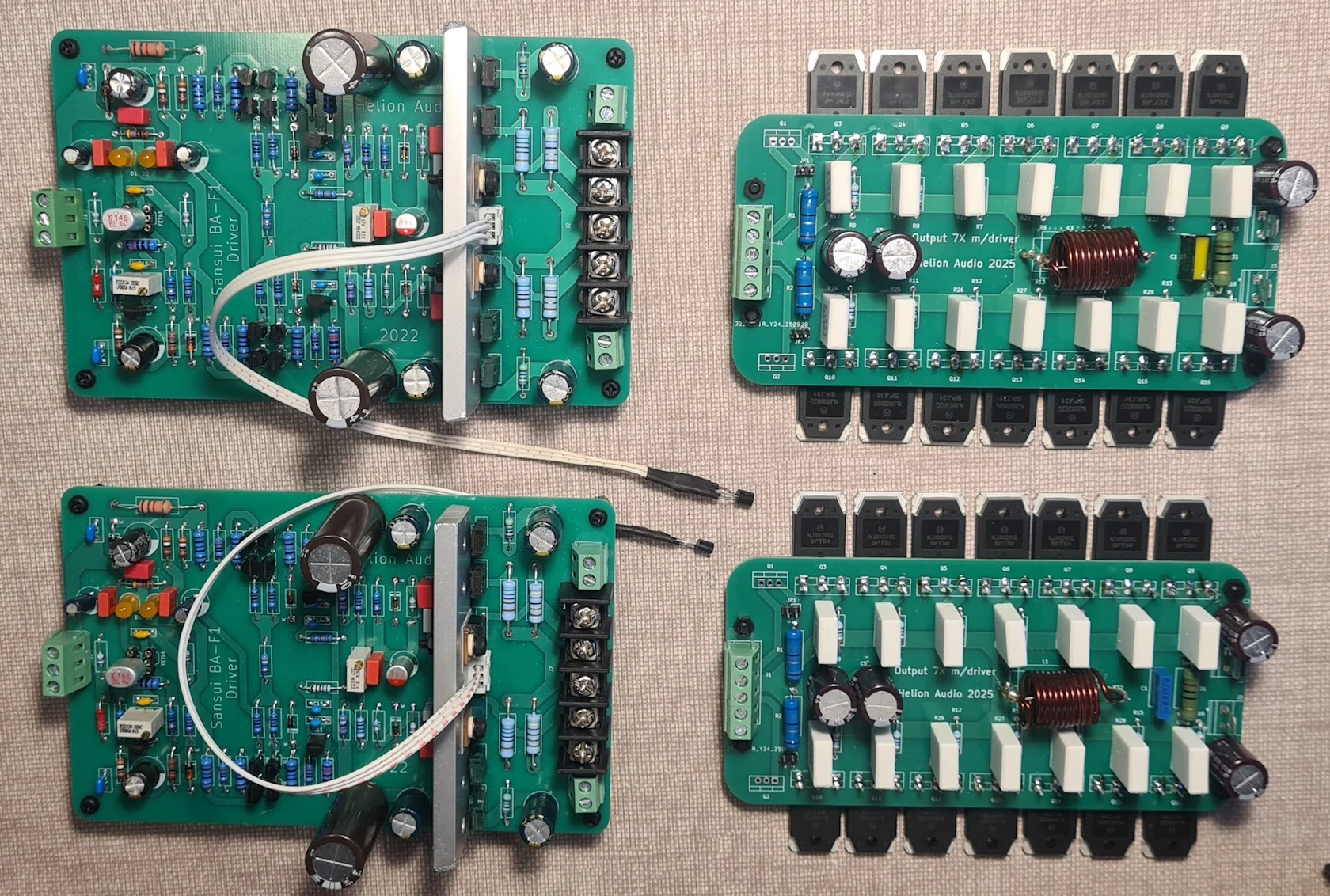
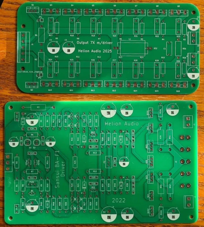
Together with a friend of mine I am about to build a Sansui BA-F1 clone. So far the PCB(s) have been made and some parts are have been ordered. This project will probably take a while and any constructive advice is welcome!
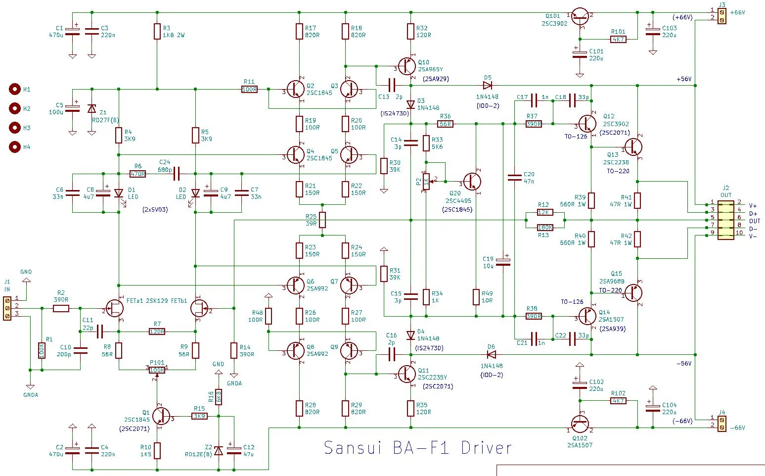
Sansui is one of the companies that uses special diode parts containing 3 and 4 separate diodes in the package. I have made a shortcut and used an LED instead. Hope this work. Anyway, it is easy to switch to 3x1N4148 if needed. The board we are using is a "driver board", i.e. a separate OPS is needed. This is also finished.
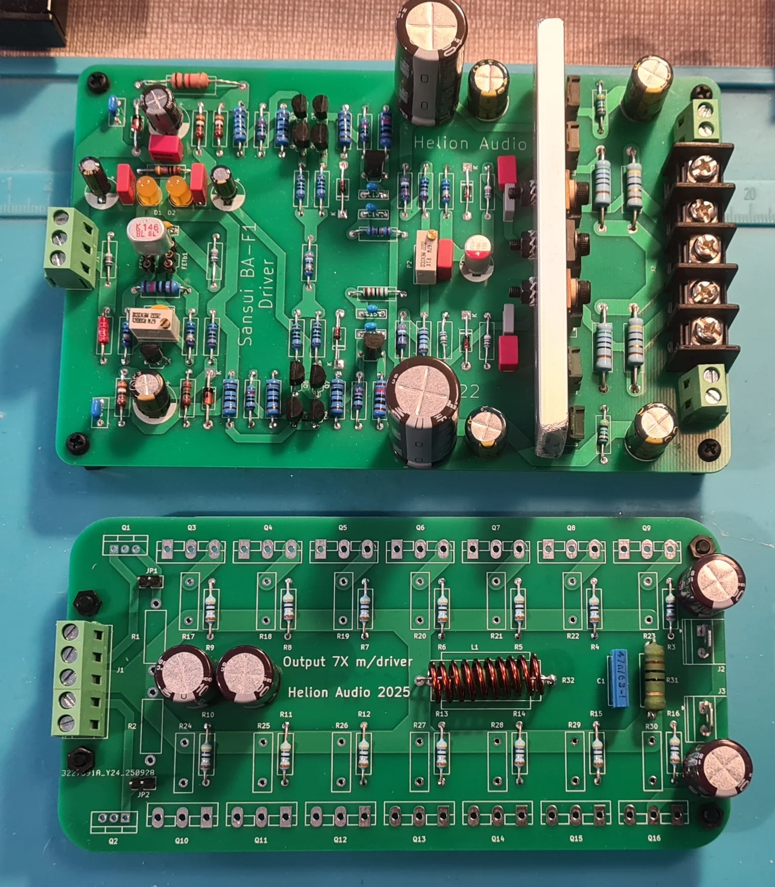
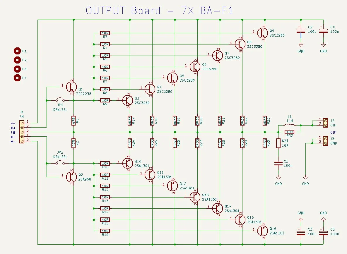
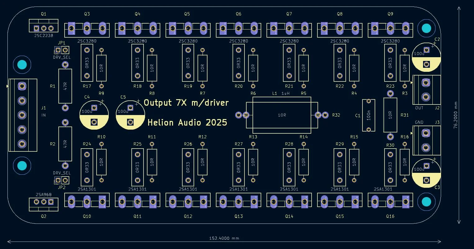
The original uses only 2+2 oputput transistors but we decided on an OPS that could use up to 7+7 output transistors. You may note the extra driver stage on the OPS. This may or may not be used according to the jumper setting. This way, the OPS could be of more universal use in other projects.
Here is what we have so far:
Driver schematic:
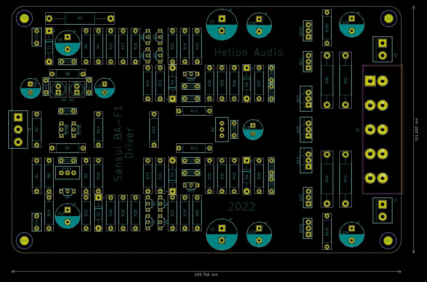
Driver PCB:
OPS schematic:
OPS PCB:
PCBs:
 morten
Together with a friend of mine I am about to build a Sansui BA-F1 clone. So far the PCB(s) have been made and some parts are have been ordered. This project will probably take a while and any constructive advice is welcome!
Sansui is one of the companies that uses special diode parts containing 3 and 4 separate diodes in the package. I have made a shortcut and used an LED instead. Hope this work. Anyway, it is easy to switch to 3x1N4148 if needed. The board we are using is a "driver board", i.e. a separate OPS is needed. This is also finished.
The original uses only 2+2 oputput transistors but we decided on an OPS that could use up to 7+7 output transistors. You may note the extra driver stage on the OPS. This may or may not be used according to the jumper setting. This way, the OPS could be of more universal use in other projects.
Here is what we have so far:
Driver schematic:
Driver PCB:
OPS schematic:
OPS PCB:
PCBs:
morten