Transistor matching---almost!

spuddo

New member
Joined
May 10, 2025
Messages
3
The test circuit shown is from the service manual of the Minimoog synthesizer.
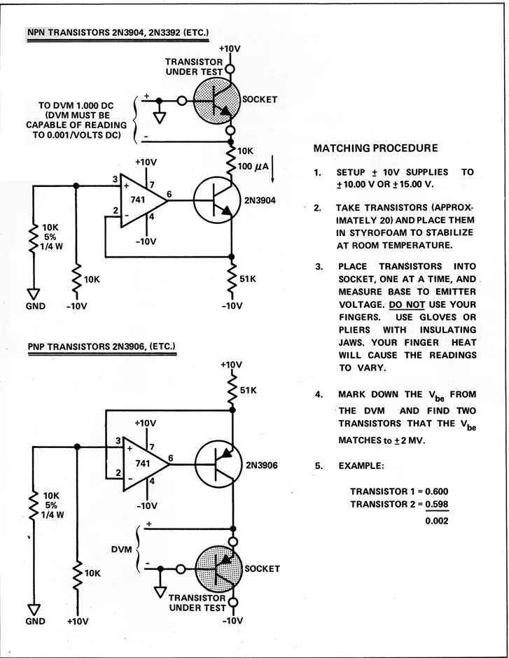
1749129652024.webp


This circuit is from the "contour / keyboard" board.
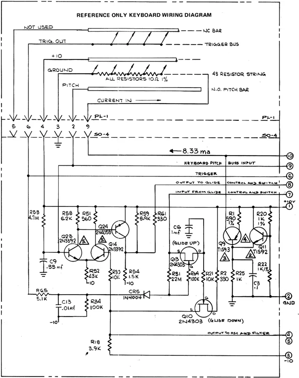
1749129828852.webp


The notes about this circuit are as follows
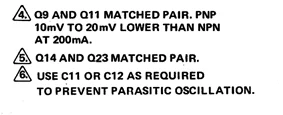
1749129980349.webp


My question is how to comply with note 4 and test at 200mA. The current shown is 100uA.

Also, I built the circuit and found that it worked better when Q9 (PNP) was 10-20 mV HIGHER than Q11 (NPN).

Any thoughts?
 
To test at 200mA like note 4 says, youll need to adjust the circuit so it actually draws that much current,, right now at 100uA, it's way off, so try lowering resistance or tweaking the supply safely. As for Q9 reading 10-20mV higher than Q11, thats likely just a mismatch or slight thermal difference, and if it's working better that way, it's probably helping bias stability. You could try matching the transistors more closely to fine-tune it.
 
HI, superjax1660.
Thanks for the reply, since posting I've learned that these old service manuals are riddled with typos and errors, either genuine cockups or planned to throw off the opposition.
A lot of patent court cases in the seventies----ARP vs MOOG
The 200mA test current seems to be BS, the main fuse is 250 mA!!!!
I got the circuit to work satisfactorily using the PNP higher Vbe than the NPN, the constant current of 8.33mA was the holy grail
If it was today, they would have used an LM317 for constant current.
Best regards
 
Back
Top