Greetings everyone!

Joined
Aug 15, 2025
Messages
11
Introducing yourself is not as easy as it seems...
I can offer complete sets (schematics, PCB, rack design, bill of materials) for two DIY projects - guitar and microphone preamplifiers, both are vacuum tube based.
 
Welcome! That sounds like a cool contribution, vacuum tube DIY projects are always a hit around here.
 
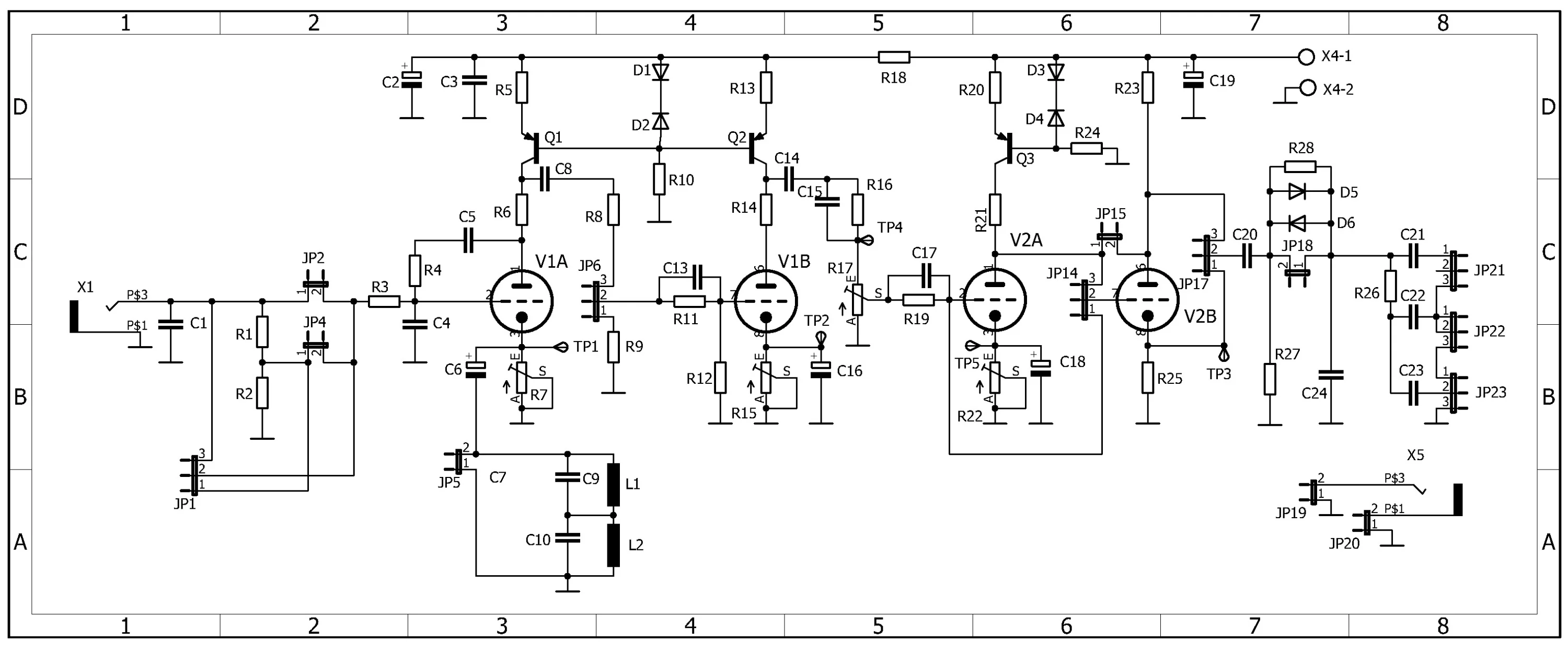
This circuit could be considered as medium-gain preamplifier. Despite that the schematic seems simple, it allows very wide spectrum of arrangements.
The circuit is designed to cover the spectrum from clean, to blues, to classic rock levels of distortion, both rhythm an lead.
The bass also is welcome, but some components should have different values from rhythm/lead version.
The primary task seems very simple - developing quite simple to DIY, reliable vacuum tube guitar preamplifier for home or/and small recording studio.
But after much experimentation with different topologies, much common works and discussions with guitarists and recordists, first came the evidence, that the devil is in the details.
In this presentation, I have no intention of explaining why one or another decision was made, maybe the product looks complicated, but not all components are necessary - it depends on the chosen solution. More explanations - directly by email; at the same time I will be happy to answer your questions in this forum too.
Picture of the assembled PCB isn't included here, but if there will be an interest, definitely it will be shown.
gpschematic.webp

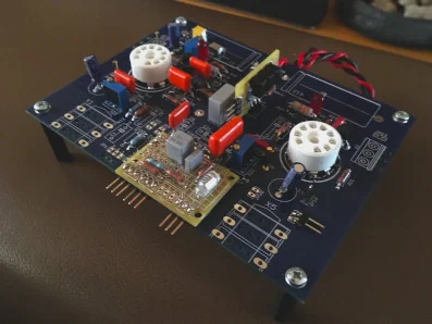
PCB (without tubes, potentiometers, input/output jacks)
IMG_0615.webp


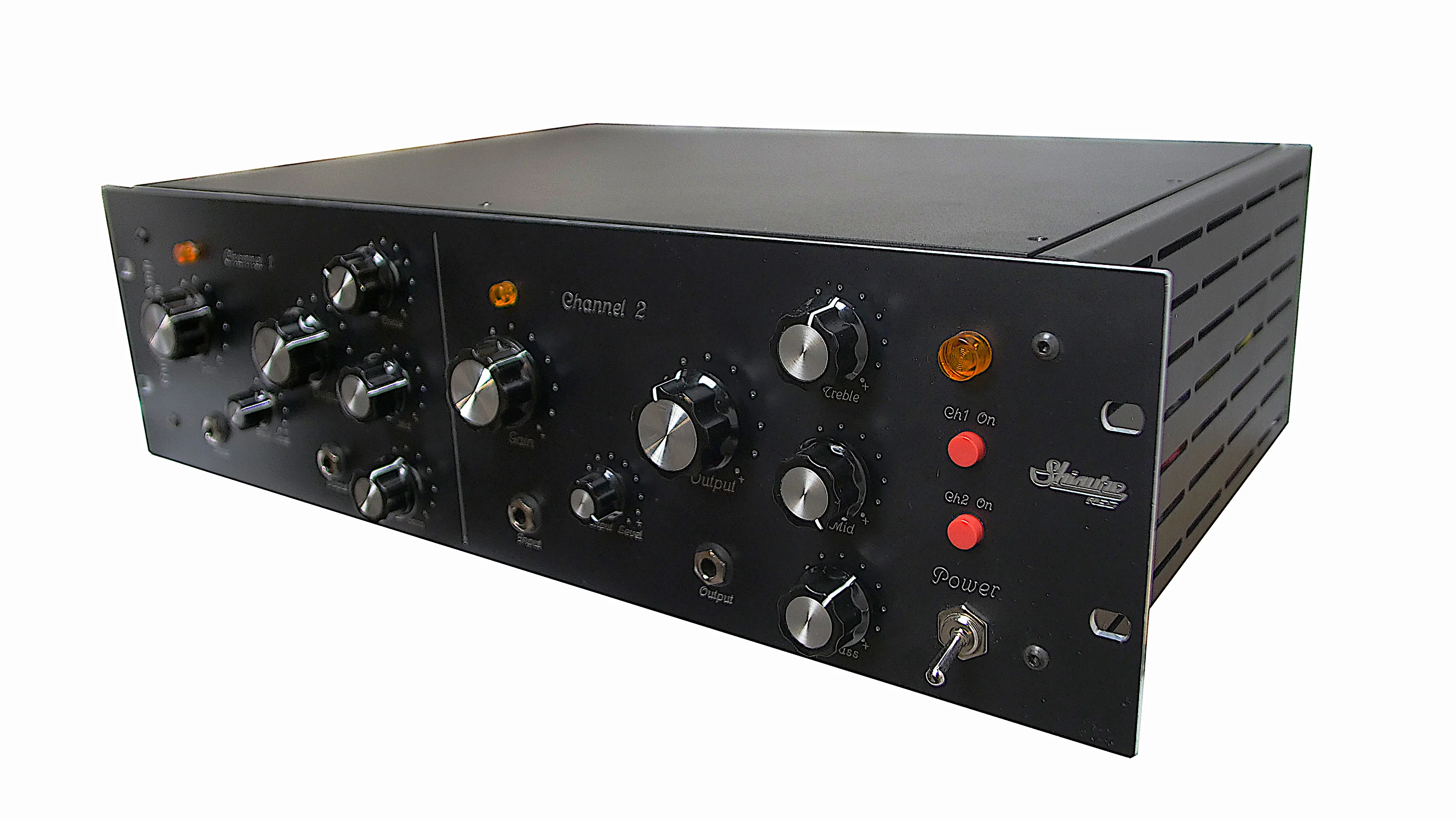
assembled unit
gpassembled.webp
 
Last edited:
I really appreciate you sharing the overview it seems like there’s a lot of careful consideration behind it.
 
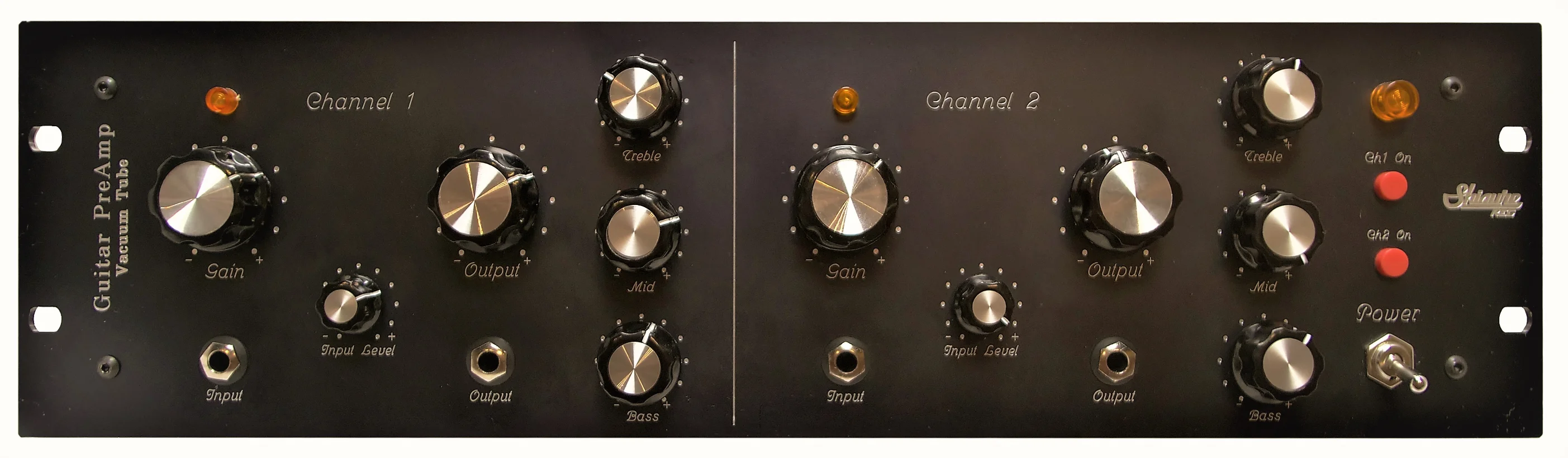
Front panel:
Input Level - rotary potentiometer(or switch), JP1 (PCB), wide range values ~500K - 1M Linear
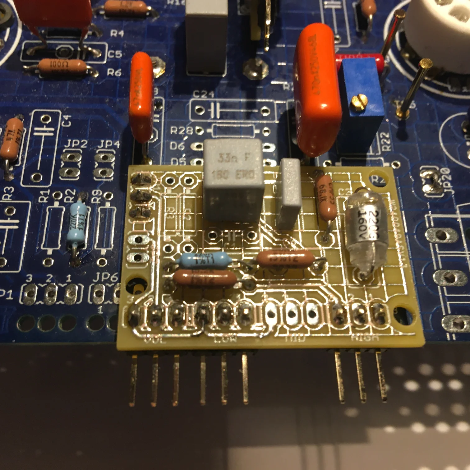
Gain - rotary potentiometer 1M Log. There are two choices - or Gain pot is directly connected to JP6, or small additional PCB with gain and tone controls (TC) is connected to JP6 - in such case tone control components R26, C21, C22, C23 not used. In my opinion, the result is better when the Gain and Bass/Treble TC are placed immediately after V1A (JP6), than when TC are at the output (R26, C21, C22, C23). The Mid control is separated from Bass/Treble, and is mounted on small PCB too, instead R17.
gpfrontpanel.webp
 
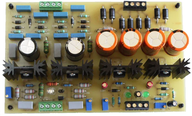
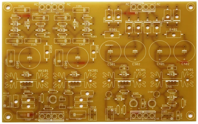
Appreciate you sharing this. The PCB looks clean and well-designed, solid capacitors and heat sinks too.
 
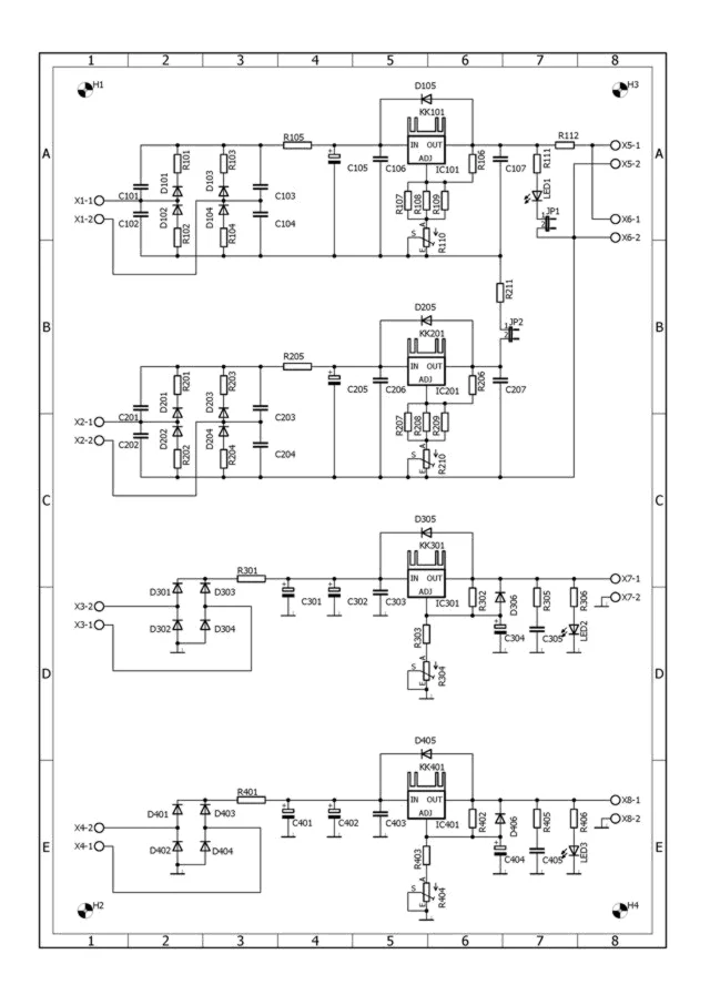
PSU schematic
I also use them on Gyraf Audio DIY G9 Tube Microphone Preamp - the G9 parameters have not become worse
Sometimes I install the HV side capacitors on bottom side of the PCB (if rack is high enough - 2U or more) to avoid extra warming from heat sinks
hvpsuschem.webp
 
PSU schematic
I also use them on Gyraf Audio DIY G9 Tube Microphone Preamp - the G9 parameters have not become worse
Sometimes I install the HV side capacitors on bottom side of the PCB (if rack is high enough - 2U or more) to avoid extra warming from heat sinks
That's great info. Do you have any advice for someone who's just starting to build their first one?
 
Seems that I should transfer this Introduction to DIY forum...
My advice could be based on such considerations:
Throughout the years, I have built many well known and popular DIY (my great respect to Gyraf Audio) preamps, EQ, but quite often when powered on for the first time, they didn't work as expected.
It seems that this problem is common for all DIY projects builders.
As a rule, DIY schematic providers emphasize the preamp action. Despite that, the characteristics of power supply used with, also have a considerable influence on the performance of the device, but this aspect of the system is one which is often being ignored. Often the power supplies which should be used with schematics are omitted. Simpliefed PSU from WEB often doesn't fit the modern possibilities (to noisy, poor long-time stability of output voltage).

In my opinion, if you are going to invest the time and expenses to build the project, why not build a project of exemplary performance in one breath?
To avoid wasting time on power supply adjustments building new schematics for each project, I have decided to implement simple, versatile, easy to build PSU design, which could be used with many DIY projects.

This PSU contains complete HV and two independent heater supplies (which could be connected consequently) on one 100x160 mm one-sided PCB.
HV supply output voltage could be trimmed up to +250 V, heater supplies also have wide trimming range, up to +35V, the value of output voltage depends on your demands.
HV supply created on integrated stabilizing circuits TL783KC (Texas Instruments) IC101 + IC201. It contains two identical stacked supplies with output voltage trimming possibility up to +125 V each.

For the first time I have tested this PSU on Gyraf Audio DIY G9 Tube Microphone Preamp - the G9 parameters have not become worse, and PSU has left to work with G9. Approx 10 yrs they work together...

I don't want to brag that this PSU is my own work - I found the schematics in a wonderful book "Burkhard Vogel Balanced Phono-Amps An Extension to the ‘The Sound of Silence’ Editions".
My personal experience also played an important role in the realization of this PSU, so to say that it was a blind copy would not be true.

If you need more information, please ask in this forum, I will be happy to answer.
 
I really appreciate you sharing this. Your experience and detailed take on DIY PSUs are super helpful especially when it comes to the power supply, which often doesn’t get the attention it deserves. It’s awesome that you’re helping others who are diving into similar projects.
 
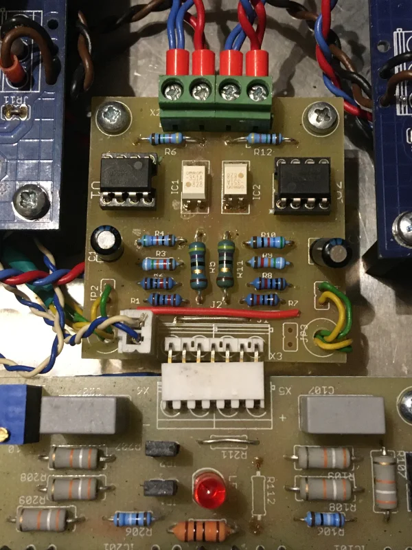
Small PCB - HV switch on/off
The purpose of the accessory is to swith on/off HV on the single channel when it is in use - the presented preamp has two channels,
Why two? Because cost of a fully assembled PSU, cost of a fully assembled preamp PCB + rack, tubes, transformers, tube sockets, potentiometers, knobs, heat sinks ... seems quite expensive.
Today I have checked the DigiKey prices of the components. The complete set for PSU only, without shipping costs would be near 60 Eur + the transformers are near 40 Eur. I still have extra "empty" PSU PCB's - one would be 10 Eur.
IMG_0624.webp
 
That makes sense going with two channels helps keep expenses low and still offers some flexibility.
Reusing those extra PSU PCBs is a clever way to cut costs without sacrificing performance
 
The preamp channels are/could be tuned differently - one channel emphasizes high frequencies, second - low (etc. for bass). One of them works from clean to light overdrive (soft clipping) mode (natural tube sound, very suitable for hollow-body guitars), other from clean to hard signal clipping (distortion). To get such flexibility trimmers instead fixed resistors are used for cathode biasing. Some familiarity to work with tube schematics is required(expected) to get the desired result. I could provide the assembled PCB with preset biasing, but it will be adjusted accordingly to my imaginations and uderstandings about the sound quality. Sometimes preamp is used as line preamp to colorize the sound with valve tones. Potentiometer connected to the JP1 allows this.

By the way I will explain the V1A biasing of the guitar preamp: if JP5 is shortened - simple RC bias. If JP5 left open and L1C9, L2C10 circuit included - more sophisticated LRC bias, which ensures more headroom and more flat frequency response. This solution is borrowed from Ovation (I hope it is not patent protected). Out of curiosity, I checked how it works with valves - I really liked the result. I advise all DIY (beginners, professionals) to try this simple (FET based) schematics .
https://www.ovationtribute.com/Ovation Schematics/Ovation_Volume_Only_Preamp/Ovation_Volume_Only_Preamp.html
 
Last edited:
Thorough explanation. I really value how clearly you laid out the biasing options and tonal flexibility. It definitely helps make the preamp’s potential easier to understand, especially for someone new to tube circuits.
 
Back
Top